
Wireless communication system

Inactive Publication Date: 2011-07-07
NAT INST OF INFORMATION & COMM TECH
View PDF3 Cites 15 Cited by
  • Summary
  • Abstract
  • Description
  • Claims
  • Application Information

AI Technical Summary

Benefits of technology

[0023]The invention with the above configuration can reliably establish synchronization by allowing every device to catch a beacon frame while suppressing power consumption by shortening the listen periods of the devices.BEST MODE OF CARRYING OUT THE INVENTION
[0024]A wireless communication system which is adapted to the wireless personal area environment will be explained as the best mode of carrying out the invention by referring to the accompanying drawings.
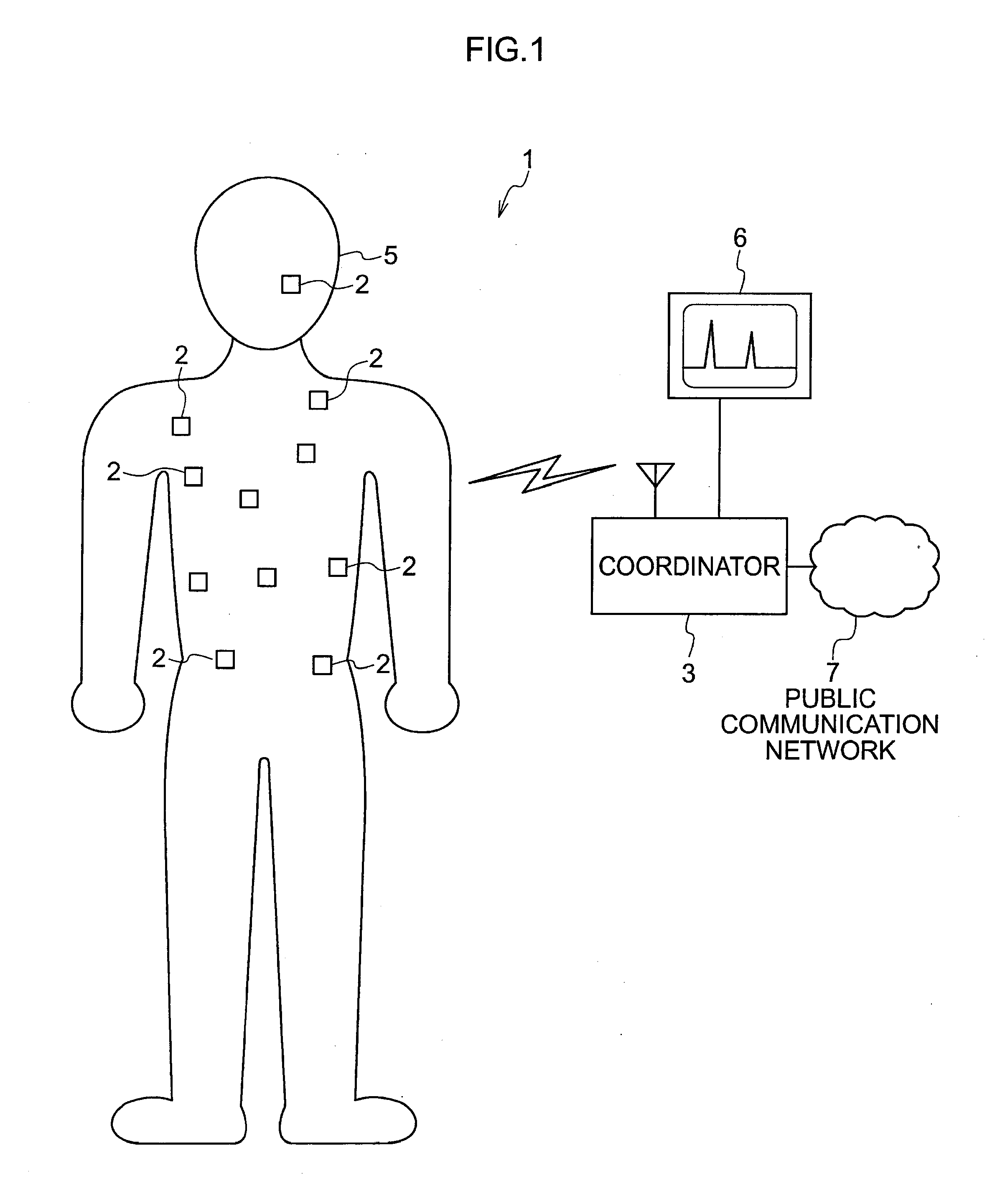
[0025]A wireless communication system 1 to which the invention is adapted, for example, includes a plurality of devices 2, and a coordinator 3 which controls the entire network as shown in FIG. 1. The wireless communication system 1 is not limited to a star type as shown in FIG. 1, and may adopt any network configuration, such as a tree type or a mesh type.
[0026]In the wireless communication system 1, the devices 2 may be, for example, implanted in a human body 5 or attached to the human body 5. The coordinator 3 may be disposed outside the human body 5. In this case, the devices 2 take pictures of the interior of the human body 5 or sense various kinds of information in the human body, and transmit the acquired data to the coordinator 3 outside the human body. The coordinator 3 receives the data, displays the data on a monitor 6 when needed, and analyzes the data to detect an abnormality of the human body. The coordinator 3 is connected to a public communication network 7 with a cable or wirelessly.
[0027]The wireless communication system 1 is premised that the coordinator 3 communicates with the devices 2 based on a time division multiple access (TDMA) protocol.
[0028]The devices 2 are assumed to be all sorts of electronic devices including at least a CPU (Central Processing Unit). Especially, the device 2 may be made by a microminiature chip including a CPU as long as it is premised that the device is implanted in or attached to the human body 5 in application. When the device 2 is used in other purposes than acquisition of various kinds of internal physical data from the device 2, for example, attached to the human body, the device may be constructed by various kinds of portable information terminals, such as a notebook type personal computer (notebook PC) and a cellular phone. The device 2 can carry out wireless communication at least with the coordinator 3, and further can carry out wireless packet communication with other devices 2 via the coordinator 3.

Problems solved by technology

However, the cables are easily tangled, and there is a restriction on the distance from a patient to the monitor due to the lengths of the cables.
An additional problem is that the presence of the cables becomes a barrier when actually performing sports.
However, those devices require a certain power on which at least a CPU (Central Processing Unit) operates and have their battery capacities or the like determined so that as the devices are attached to a human body, they should be always operable even in an unstable state.
In case that the internal physical data transmitted via the devices needs to be monitored continuously, the batteries of the devices are consumed soon.
Especially, it is neither economical nor practical to replace the battery of a device frequently once implanted in a human body.

Method used


Image

  • Wireless communication system
  • Wireless communication system
  • Wireless communication system

Examples


first embodiment

[0057]An embodiment of the wireless communication system 1 to which the invention is adapted will be described below.

[0058]Table 1 shows an example of various parameters in the wireless communication system 1.

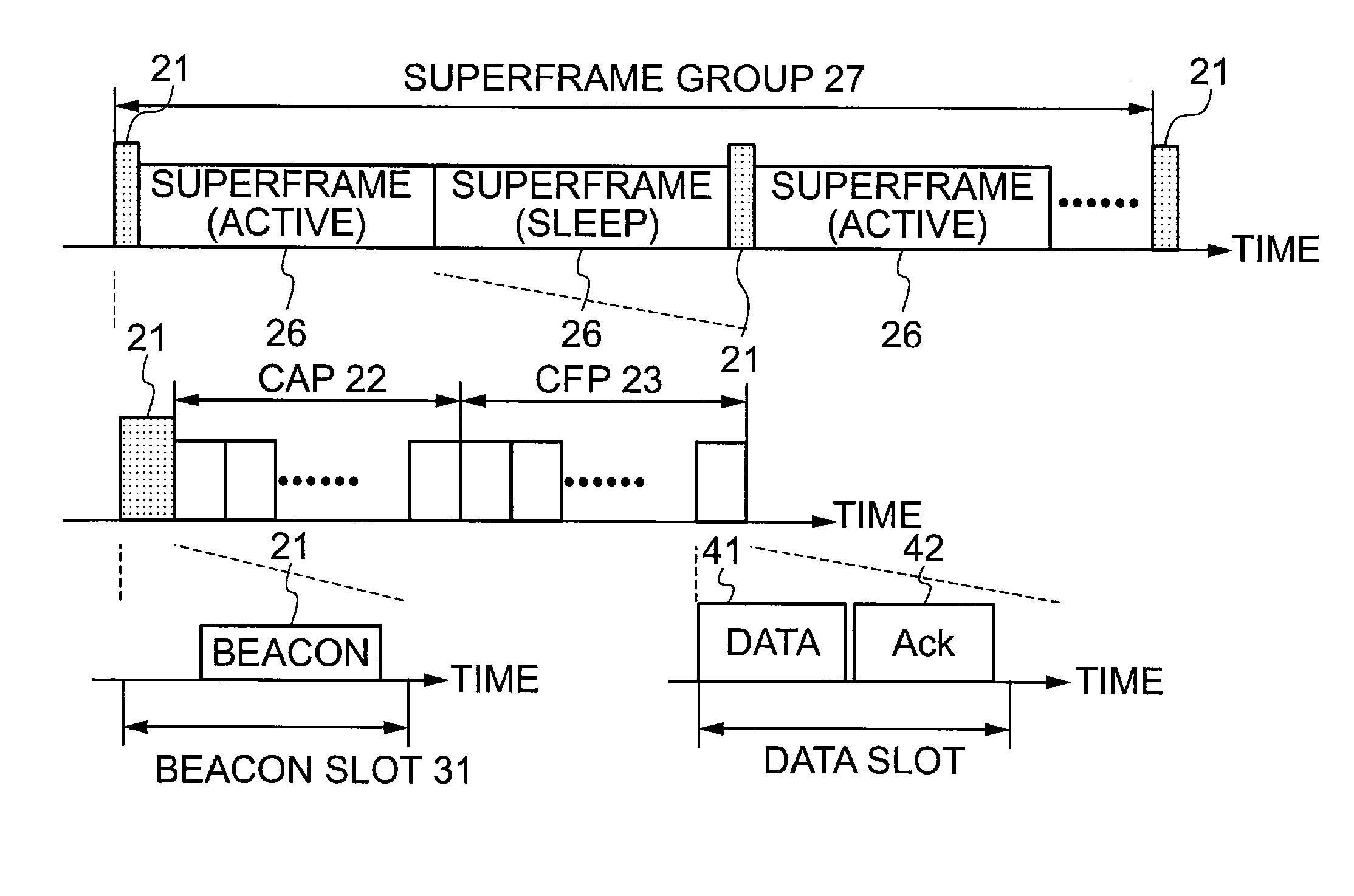
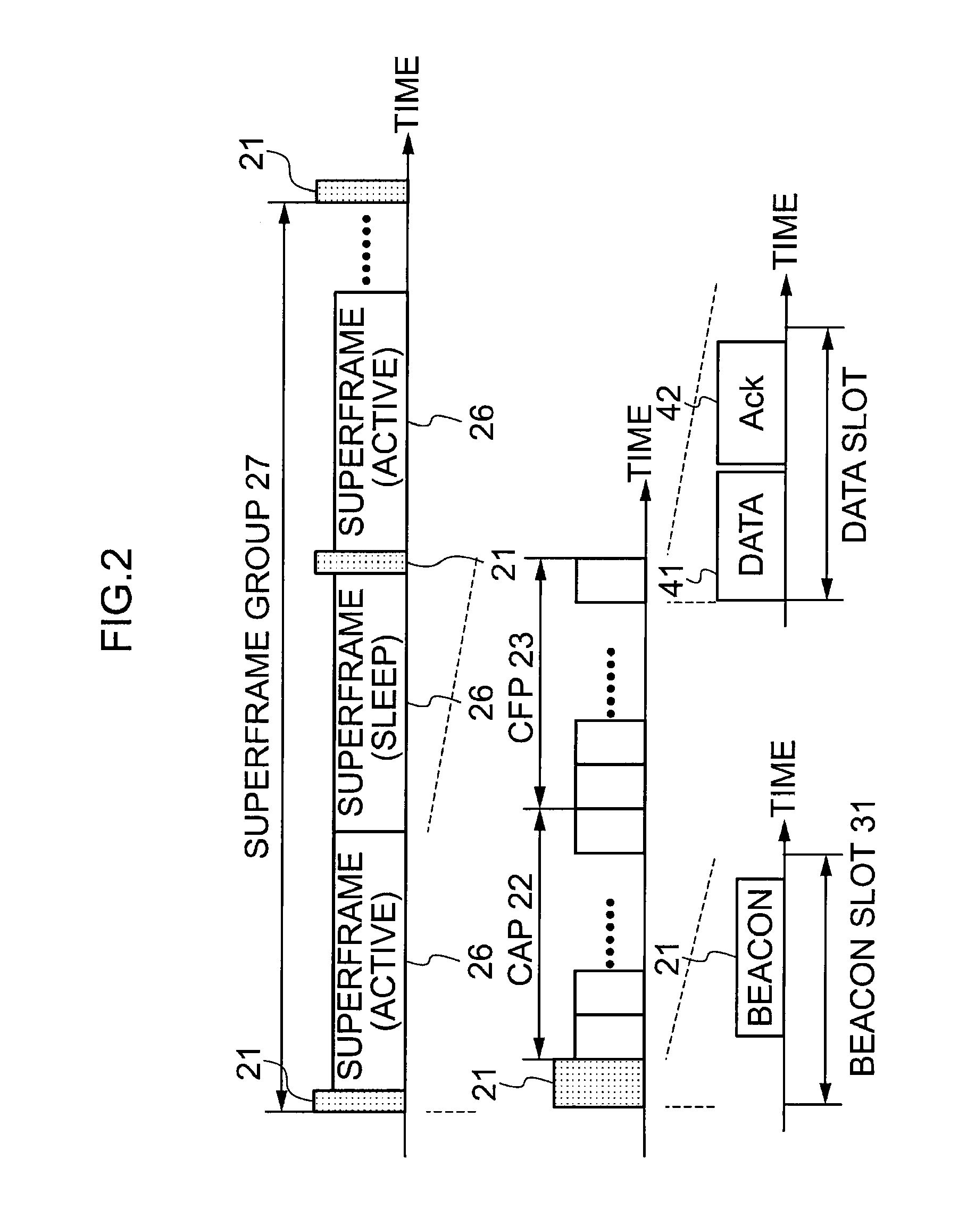
TABLE 1Parameter nameValuesDescriptionData rate1MbpsData rate of the physical channelTurn-around32μsConstant time for node to switch betweentimetransmit and receive stateTs2msConstant duration of a time slotTd1msConstant position of frame delimiter inbeacon relative to the end of slot boundaryG1-16Number of superframes in a superframegroupCA5-16Number of slots in the CAPCF1-10Number of slots in the CFP

[0059]Table 2 shows an example of the structure of the beacon frame.

TABLE 2Section nameBitsDescriptionPreamble sequence32~1384Unique synchronization code, variable duration per Eq. 1Frame delimiter8Delimiter to indicate the start of beacon frameFrame length8Total length of beacon frame in bytesMAC layer header56MAC header of beaconTime stamp8Sequence of the superframe in the super...


PUM


Abstract

A wireless communication system includes a coordinator (3) that broadcasts a beacon (21) having at least a preamble part (32) and a payload part (33), and a plurality of devices (2) each of which is synchronizable with at least the coordinator (3) by listening to the beacon (21) through a listen period set based on an own reference clock. The coordinator (3) fixes a position of the end of the beacon (21) with respect to a beacon slot constituting a superframe, and generates the beacon (21) where a start of a preamble part (32) is extended toward a start of the beacon slot over a time To. The devices (2) are synchronized with the coordinator (3) via an end time of the beacon slot detected from an end time of the preamble part (32) in the beacon frame.

Description

TECHNICAL FIELD[0001]The present invention relates to a wireless communication system which enables wireless communication between a plurality of devices attached to a human body or implanted therein and a coordinator.BACKGROUND ART[0002]In diagnosing a human body, the blood pressure and cardiogram are particularly important parameters in discriminating the current health state of a patient. There also is a case where an athlete wants to measure his / her physical conditions during sports to improve the skill or the quality of training.[0003]In this respect, there is proposed a cable communication system in which devices are attached to a human body to transmit various kinds of information measured by the devices to a wired monitor, and the information is grasped through monitor images. However, the cables are easily tangled, and there is a restriction on the distance from a patient to the monitor due to the lengths of the cables. An additional problem is that the presence of the cabl...

Claims


Application Information

Patent Timeline
IPC IPC(8): H04B7/212H04J3/06
CPCH04W52/0216H04W74/004H04W56/00Y02D30/70
Inventor ZHEN, BINLI, HUAN-BANGKOHNO, RYUJI
Owner NAT INST OF INFORMATION & COMM TECH
Learn More