Flow-synchronous field motion refrigeration

a technology of flow-synchronous field and refrigeration, which is applied in the direction of machine operation mode, heat pump, lighting and heating apparatus, etc., can solve the problems of reducing the range of useful temperature spans, reducing the use of different designs so far to practice for mce, and requiring a large physical magnetic field to raise or lower the entire temperature profile. , to achieve the effect of improving heat transfer, improving the useful temperature span, and reducing the physical size of the magn

Inactive Publication Date: 2012-09-06
HASSEN CHARLES N
View PDF9 Cites 75 Cited by
  • Summary
  • Abstract
  • Description
  • Claims
  • Application Information

AI Technical Summary

Benefits of technology

[0010]The flow-synchronous field motion method in accordance with the present invention provides several important advantages over prior art in managing heat flow through the system: (1) The method provides improved range of useful temperature spans compared to conventional designs. (2) The method provides improved heat transfer per cycle of the refrigerator compared to conventional designs. (3) The method allows smaller magnet physical size relative to the active regenerator bed length compared to conventional designs, or for smaller electrode size to be employed in electro-caloric heat pumps operated on the same principle. (4) The magnet or electric field can move at a constant relative speed without stopping in position over the active regenerator bed, making this approach ideally suited for improving the simplicity, and hence lowering cost and increasing reliability, of rotary-style active regenerator or linear-style active regenerator beds, without compromising performance. (5) The transient period during which the system approaches its steady state

Problems solved by technology

Although researchers are only beginning to build devices for ECE applications, there are many different designs so far reduced to practice for MCE refrigerators, some with single active regenerator units or multiple active regenerator units; some move the active regenerator into and out of a stationary magnetic field; some move the magnet instead and keep the active regenerator stationary.
One significant drawback to the conventional methods of

Method used


Image

  • Flow-synchronous field motion refrigeration
  • Flow-synchronous field motion refrigeration
  • Flow-synchronous field motion refrigeration

Examples


example 1

Model the Conventional Approach of Non-Synchronous Flow

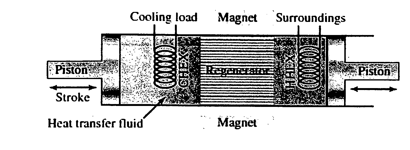
[0042]In this case, we first raise the temperature across the bed by applying the magnetic field, then pump cold fluid in from the cold end to the hot end, then lower the temperature by removing the magnetic field, then pump fluid back from the hot end to the cold end.

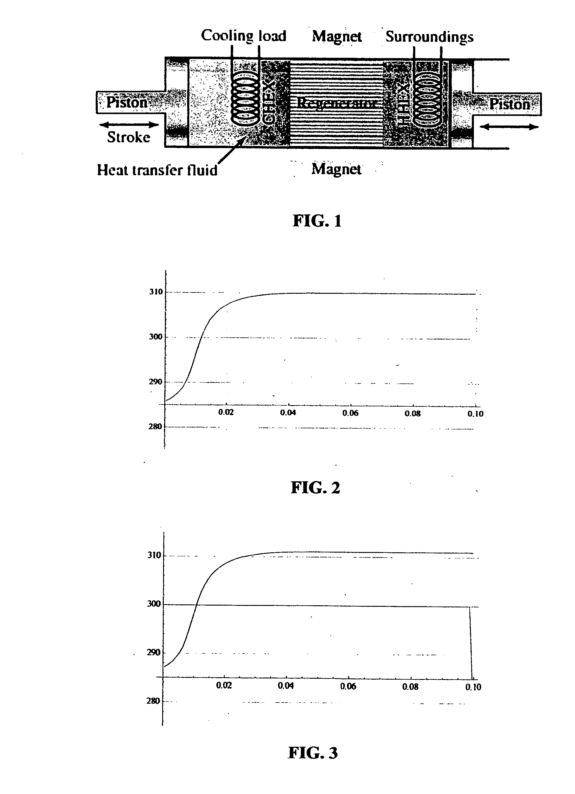
[0043]In this baseline case, 287 Joules are removed from the cold side, and 294 Joules are discharged at the hot side per cycle (difference=7 Joules). This difference may represent the minimum work required to be done by heat pump in terms of mechanical work to move the magnet, though some experimental verification of this assumption is needed to confirm it. Note that the amount of heat transferred per cycle is much higher for this zero-differential case than for the 25 degree-differential case modeled in FIG. 2 through FIG. 6, in which only 94 joules were transferred.

[0044]There are several variables to consider:[0045](1) Ratio of heat capacity of fluid to heat ca...

example 2

Forward Bias, Fluid Moves Faster than Field

[0049]In this case, a hot zone emerges from the leading edge of the moving magnet, with the temperature of the hot zone growing progressively higher as the motion proceeds. There is a limit to the height of the hot zone, which is a function both of the relative velocity of the fluid and the magnet, and the heat capacity ratio of the fluid to the regenerator. The trailing cold zone moves forward with the magnet as well, so the fluid gets progressively colder in the cold zone as the motion proceeds. Forward bias produces the sharpest peaks, and the highest absolute values of temperature change from low to high. It is possible to push fluid so quickly, that the cold side temperature “breaks through” the leading edge of the moving magnetic field, a condition that diminishes overall efficiency. In our forward bias example, the velocity of the magnet is 75% of the fluid velocity, and the cold tail pushes about ⅓ of the distance from the trailing ...

example 3

Neutral Bias, Fluid Moves at Same Speed as Field

[0051]This is the limiting case of forward bias theoretically, but in fact one begins to observe behavior associated with reverse bias synchronization due to the thermal mass of the regenerator and heat transfer fluid. We selected a fluid to regenerator volume ratio of 3:1 (75% porosity) for this model case. A greater ratio of fluid heat capacity to regenerator heat capacity produces less stretching of the hot pulse and of the cold pulse as the field moves across the AMR bed.

[0052]In this neutral bias case, the cold side heat transfer is 283.6 Joules, and the hot side heat transfer is 295.6 Joules (difference=12 Joules).

[0053]It is interesting to note that the plateau height for the temperature difference attained in the neutral bias case is almost exactly equal to the isentropic temperature change for the 290 degree starting temperature (delta T=3.2 K).


PUM


Abstract

An improved method to manage the flow of heat in an active regenerator in magnetocaloric or an electrocaloric heat-pump refrigeration system, in which heat exchange fluid moves synchronously with the motion of a magnetic or electric field. Only a portion of the length of the active regenerator bed is introduced to or removed from the field at one time, and the heat exchange fluid flows from the cold side toward the hot side while the magnetic or electric field moves along the active regenerator bed.

Description

[0001]This application claims the benefit of U.S. Provisional Application No. 61 / 276,895, filed Sep. 17, 2009, incorporated herein by reference.[0002]This invention was made in part with US Government support under Small Business Innovative Research (SBIR) Department of Energy Contract No. DE-FG02-07ER84943. The Government has certain rights in the invention.FIELD OF THE INVENTION[0003]This invention pertains to the field of magnetocaloric or electrocaloric refrigeration, and to the use of active regenerators. More specifically, this invention relates to methods for management of the flow of heat exchange fluid in heat pumps employing active regenerators, to enhance performance and reduce the cost of such devices.BACKGROUND OF THE INVENTION[0004]The Magneto-Caloric Effect, or MCE, is a property of certain materials, as a result of which property those materials change their temperature when subjected to a change in the magnetic field in which they operate. A related effect known as ...

Claims


Application Information

Patent Timeline
IPC IPC(8): F25B21/00
CPCF25B21/00F25B30/00Y02B30/52F25B2321/002Y02B30/66F25B2321/001Y02B30/00
Inventor HASSEN, CHARLES N.
Owner HASSEN CHARLES N
Why Eureka
Try Eureka