

Wireless power receiver, wireless power transmission system, and power controller
a wireless power transmission system and power controller technology, applied in the direction of impedence networks, circuit arrangements, inductances, etc., can solve the problem of small electric power, and achieve the effect of easy adjustment of the magnitude of the receiving power
- Summary
- Abstract
- Description
- Claims
- Application Information
AI Technical Summary
Benefits of technology
Problems solved by technology
Method used
Image

Examples
first embodiment
[0062]FIG. 7 is a circuit diagram of a connecting portion between the power controller 400 and loading circuit 140 in the first embodiment. In the first embodiment, the real number part R of the impedance Z is set as a control target. It is assumed here that Z=R+jX, ZL=RL, and R=RL are satisfied. The power controller 400 measures the power (receiving power) of the resistance RL and searches for a resistance value at which the receiving power becomes the maximum while changing the value of the resistance RL.
[0063]Voltage Vo applied to the resistance RL is input to a mixer 402. The magnitude of current Io flowing in the resistance RL is measured as a voltage value by a transformer T1 and is then input to the mixer 402. More specifically, a voltage value of Io×R5 is applied to a parallel resistance R5 of the transformer T1 and this voltage value is input to the mixer 402. As a result, the mixer 402 outputs Vo×Io×R5 which is a value obtained by multiplying the two inputs (Vo and Io×R5)....
second embodiment
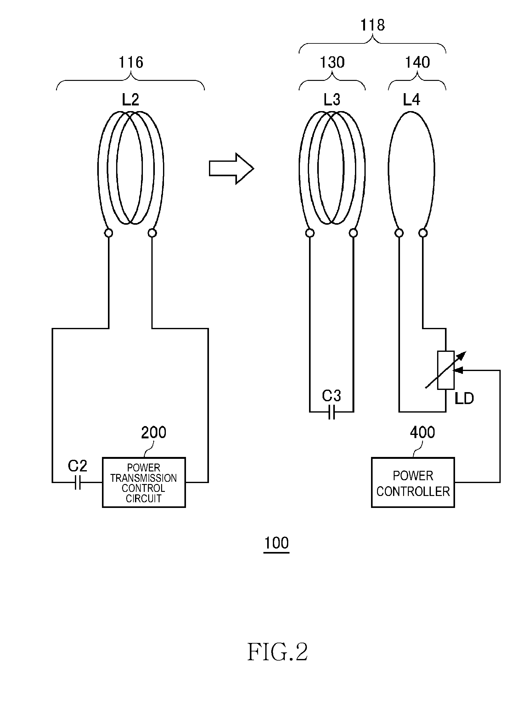
[0090]FIG. 10 is an equivalent circuit diagram of the wireless power transmission system according to a second embodiment. For simplification, the inductances of both the feeding coil L2 and receiving coil L3 are assumed to be L, and the electrostatic capacitances of both the capacitor C2 and capacitor C3 are assumed to be C, as in the case of the first embodiment. The mutual inductance between the feeding coil L2 and receiving coil L3 is assumed to be Lm. In the second embodiment, both the resistance component (real number part) and reactance component (imaginary number part) of the impedance Z are set as control targets.
[0091]In the second embodiment, a reactance unit 110 is newly provided. The reactance unit 110 includes a first reactance unit 120, a second reactance unit 122, and a third reactance unit 124. The power controller 400 adjusts the reactance of the reactance unit 110 to thereby maximize the receiving power at the load LD.
[0092]For clearing noise, a coil L6 and a capa...
third embodiment
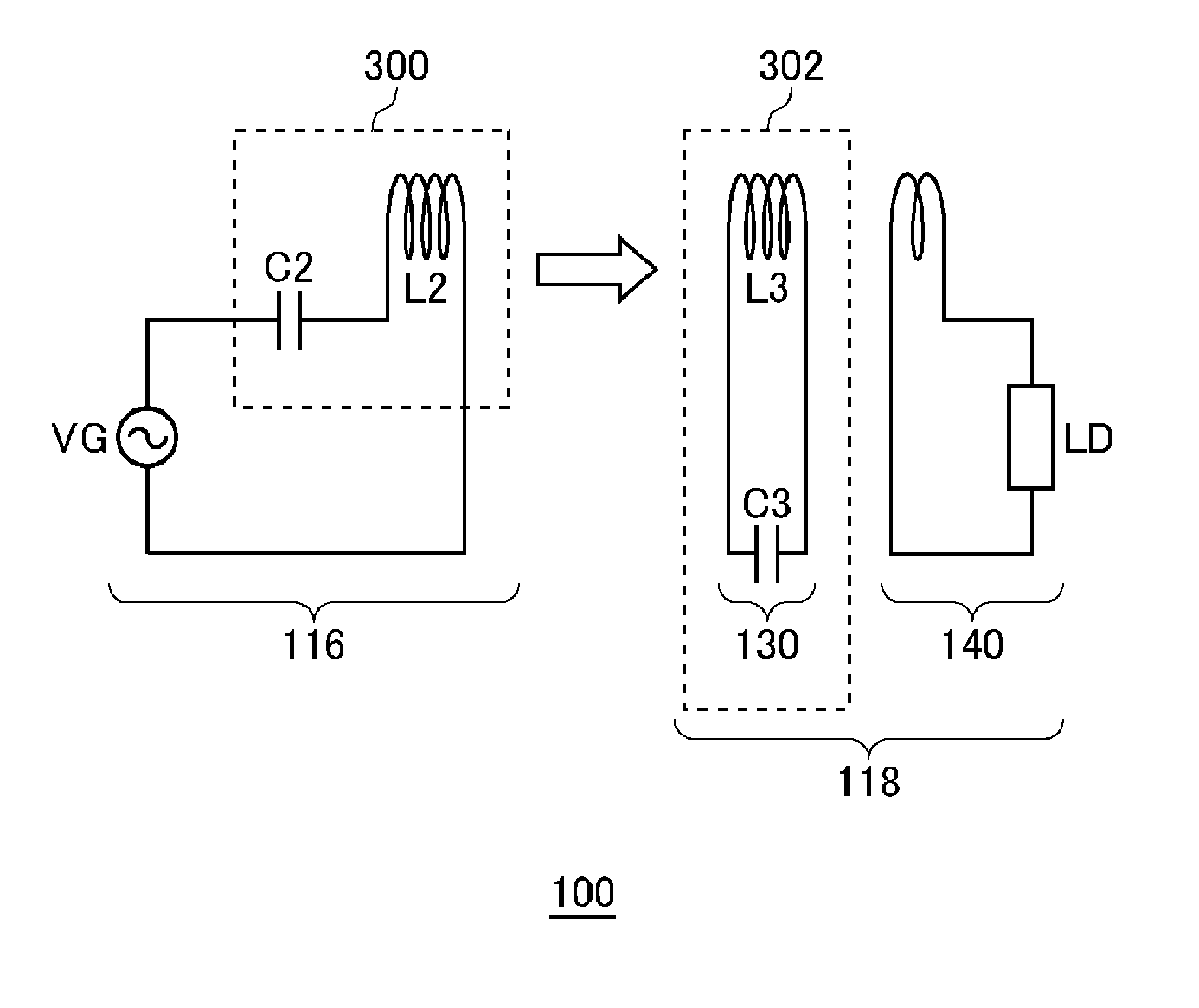
[0117]FIG. 19 is a view illustrating operation principle of the wireless power transmission system 100 according to a third embodiment. The wireless power transmission system 100 according to the third embodiment includes the wireless power feeder 116 and wireless power receiver 118. However, although the wireless power receiver 118 includes the power receiving LC resonance circuit 302, the wireless power feeder 116 does not include the power feeding LC resonance circuit 300. That is, the feeding coil L2 does not constitute a part of the LC resonance circuit. More specifically, the feeding coil L2 does not form any resonance circuit with other circuit elements included in the wireless power feeder 116. No capacitor is connected in series or in parallel to the feeding coil L2. Thus, the feeding coil L2 does not resonate in a frequency at which power transmission is performed.
[0118]The power feeding source VG supplies AC current of the resonance frequency fr1 to the feeding coil L2. T...
PUM
 Abstract
Description
Claims
Application Information