
Charging module

Inactive Publication Date: 2012-09-06
TENNRICH INT
View PDF2 Cites 38 Cited by
  • Summary
  • Abstract
  • Description
  • Claims
  • Application Information

AI Technical Summary

Benefits of technology

[0008]In view of the shortcomings of the prior art, the inventor(s) of the present invention based on years of experience in the related industry to conduct extensive researches and experiments, and finally developed a charging module as a principle objective so that a junction effect between a power supply device and an electronic product can be retained, and the electronic product can be quickly taken and used.
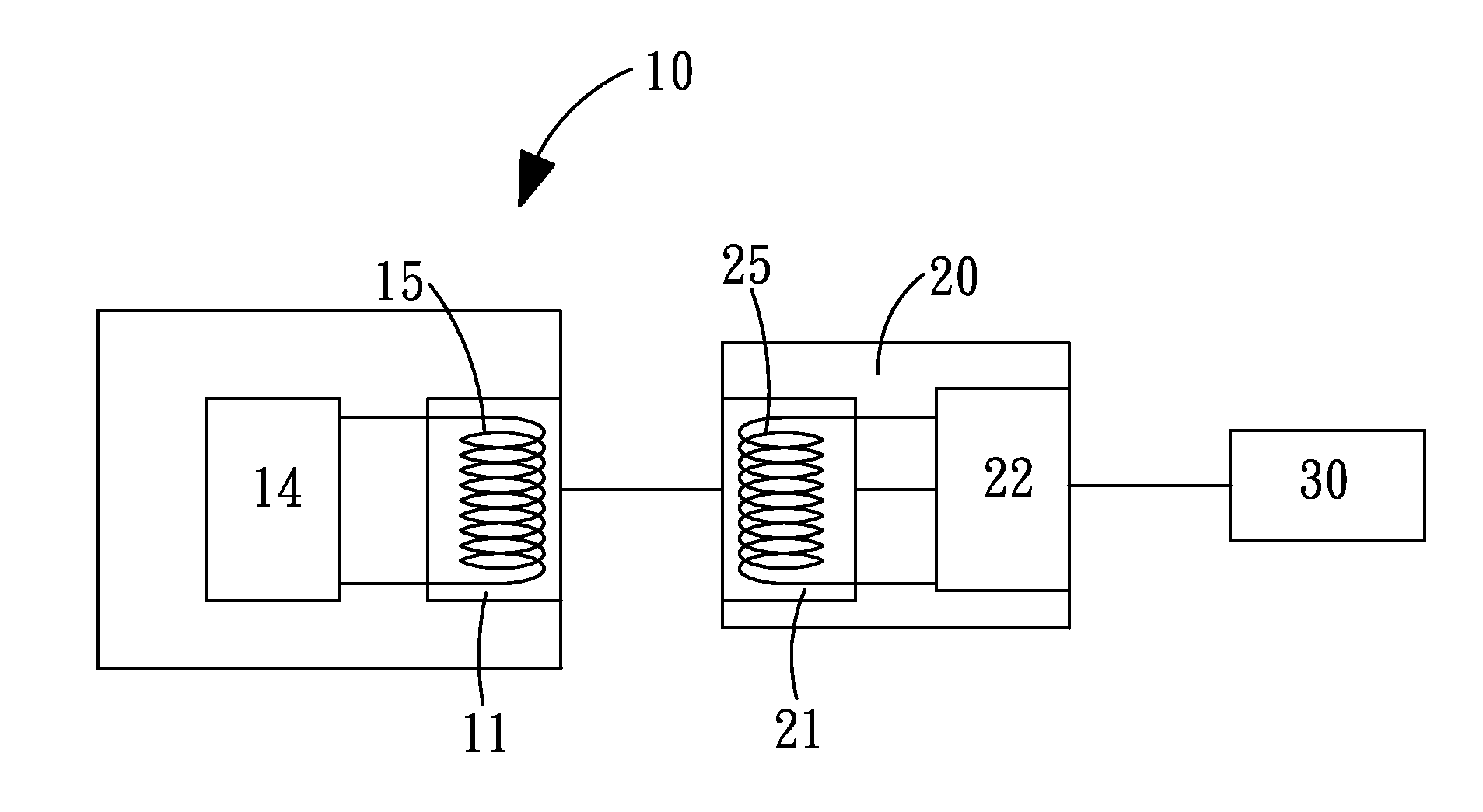
[0010]When the charging module of the invention is used, the power supply device is electrically connected to the electronic product through the adapter. Power from the power supply device is delivered to the electronic product. Moreover, a desired junction effect between the adapter and the power supply device can be retained through the attraction of the first and second magnetic attraction components. The electronic product can be separated from the power supply device by slightly imposing forces. The electronic product can be quickly taken by a user without influencing the operation of the electronic product.

Problems solved by technology

), the electronic products are connected with wires which cause inconvenience.

Method used


Image

  • Charging module
  • Charging module
  • Charging module

Examples


Embodiment Construction

[0032]The foregoing and other technical characteristics of the present invention will become apparent with the detailed description of the preferred embodiments and the illustration of the related drawings.

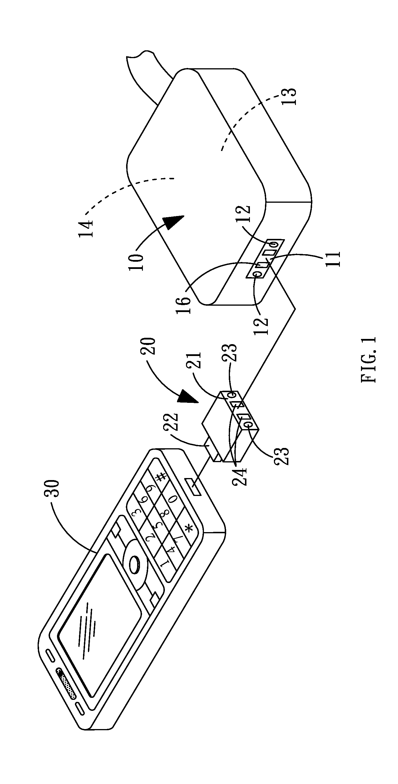
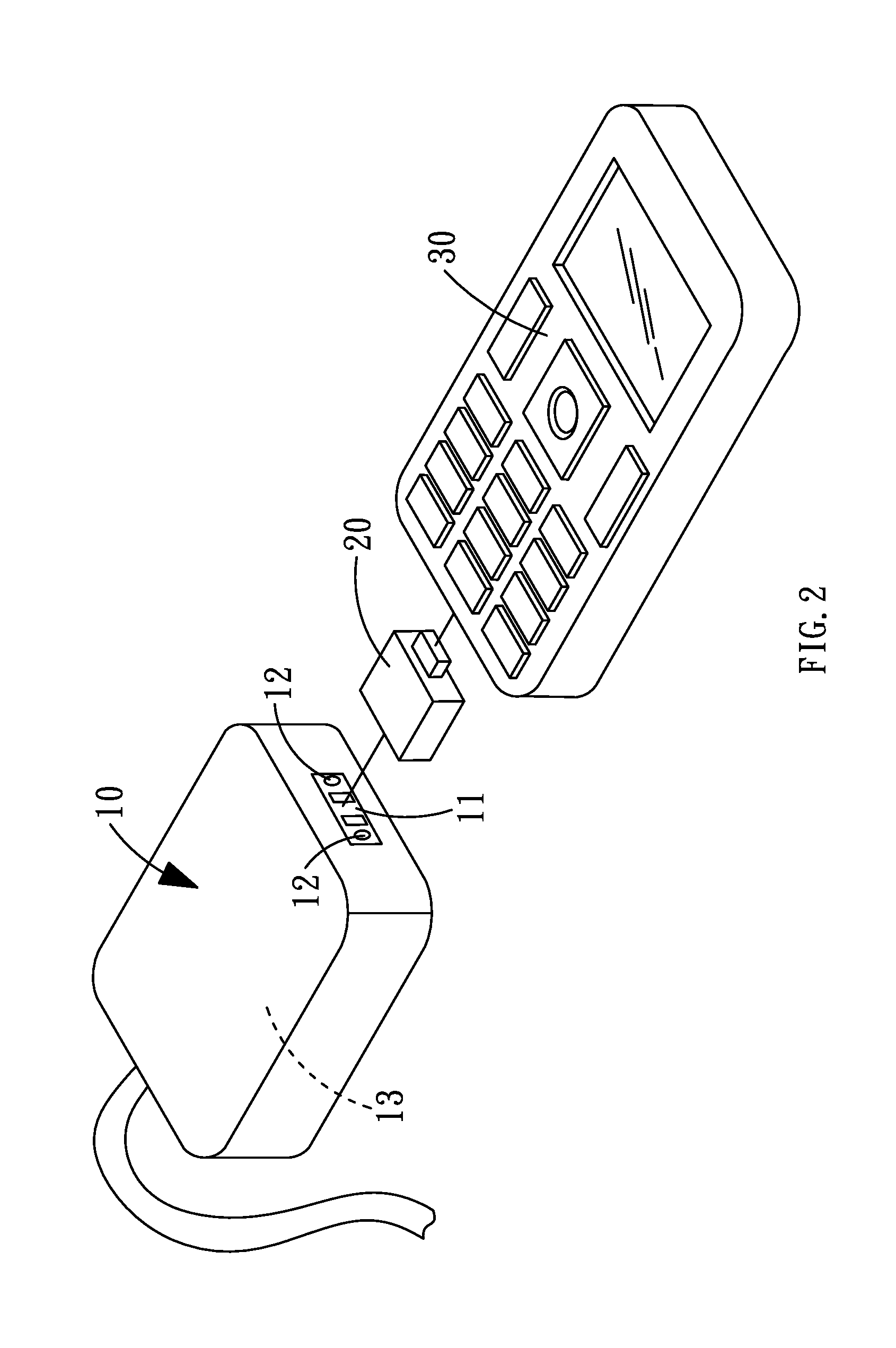
[0033]With reference to FIG. 1 for a three-dimensional drawing of a charging module in accordance with a first embodiment of the invention and with reference to FIG. 2 for a three-dimensional drawing of a charging module at another visual angle in accordance with a first embodiment of the invention are depicted. The charging module of the invention comprises a power supply device 10 and at least one adapter 20.

[0034]The power supply device 10 is used for supplying power required for charging or operating an electronic product 30. A first coupling portion 11 is disposed on a main body to electrically connect the adapter 20, and a first magnetic attraction component 12 is disposed to the first coupling portion. The adapter 20 has a second coupling portion 21, which is electrically c...


PUM


Abstract

A charging module comprises a power supply device and at least one adapter, wherein a first and second magnetic attraction components, which are attracted to each other, are respectively disposed to a coupling place between the adapter and the power supply device. While in use, the power supply device is electrically connected to an electronic product through the adapter. Power from the power supply device is delivered to the electronic product, and attraction of the first and second magnetic attraction components is utilized to retain the junction effect between the adapter and the power supply device. The electronic product can be separated from the power supply device by slightly imposing forces. The electronic product can be quickly taken by a user without influencing the operation of the electronic product.

Description

BACKGROUND OF THE INVENTION[0001]1. Field of the Invention[0002]The present invention relates to a charging module, and more particularly to the charging module capable of retaining the junction effect between a power supply device and an electronic product and rapidly using the electronic product.[0003]2. Description of the Related Art[0004]Since the technology is continuously developed, people may require electronic products to have more functions, especially for consumer electronics. A conventional electronic product having a larger size (e.g. a compact disc player, a telephone or a desktop computer) is simplified to form a portable electronic product with high efficiency (e.g. a multimedia player (MPEG Audio Layer-3, MP3), a mobile phone or a laptop computer) to increase the efficiency for people in daily life.[0005]The power required for the foregoing portable electronic products is mostly adapted with a rechargeable battery such as a nickel-metal hydride battery or a lithium c...

Claims


Application Information

Patent Timeline
IPC IPC(8): H02J7/00
CPCH02J7/0054H02J7/0042H02J7/342
Inventor CHEN, SHIH-HUILIN, CHIN-TIEN
Owner TENNRICH INT
Learn More