Electro-thermal heating system

a heating system and electro-thermal technology, applied in the direction of electric heating, air heaters, fluid heaters, etc., can solve the problems of reducing the economic viability of gas-fired applications, reducing the economic viability of such furnaces, and correspondingly increasing the price, so as to achieve low cost, simple design, and low cost

Inactive Publication Date: 2012-09-06
DYNACURRENT TECH
View PDF9 Cites 7 Cited by
  • Summary
  • Abstract
  • Description
  • Claims
  • Application Information

AI Technical Summary

Benefits of technology

[0012]The advantage of the present invention is that it provides an improved, environmentally friendly electro-thermal heating system which has a generally uncomplicated and simple design, which possesses a minimal footprint, and which has a housing which can circulate and heat a flow of coolant therein. The housing can then be interconnected with piping to form a closed fluid flow circuit, whereby heat from the heated coolant can be used to heat a space remote from the housing. Further, the system can be integrated with pumps, and connected to a power source, whereby the closed fluid flow circuit can be used to circulate and radiate heat in a variety of applications, such as radiant floor heating, home heating, and so forth.
[0013]Yet another advantage of the present invention is to provide an improved electro-thermal heating system having a housing with an inlet for permitting a flow of coolant into and throughout the housing and an outlet for permitting a transfer of heated coolant out of the housing, wherein a diameter of the inlet is greater than a diameter of the outlet so as to keep coolant in the housing longer to heat it, therefore heating the coolant in a faster and more efficient manner.
[0014]Yet another advantage of the present invention is to provide an improved electro-thermal heating system having a second housing interconnected, via piping, to the first housing, the second housing also containing a plurality of openings therein for insertion of additional electric heating elements to heat the coolant in the flow circuit in a faster, efficient manner.

Problems solved by technology

However, as the demand for oil has risen sharply in the last decade, the price has correspondingly risen sharply, reducing the ability of such furnaces to be economical to the home or business owner.
However, much as has occurred with oil, natural gas has also seen large price increases in the last couple of years, which has also reduced the economical viability of gas-fired applications.
It is also well known to heat homes or spaces using, for example, electrical baseboards, but, as hydro rates have risen quite sharply recently, and can be expected to continue upwardly in the future, these types of devices are not necessarily economical also.
In addition, heating systems such as furnaces can require a large footprint, and take up an inordinate amount of space.
However, these arrangements feature electrical elements that are internally positioned and firmly set within a tank or chamber, and do not allow for easy removal of the electrical element from the pre-heater without complete disassembly, or destruction, of the pre-heater, should maintenance or replacement of the electrical element be required.
In such maintenance or replacement situations, the entire pre-heater would be required to be removed to access the internal electrical element, thereby making maintenance and replacement of such pre-heater components difficult and complicated.

Method used


Image

  • Electro-thermal heating system
  • Electro-thermal heating system
  • Electro-thermal heating system

Examples


Embodiment Construction

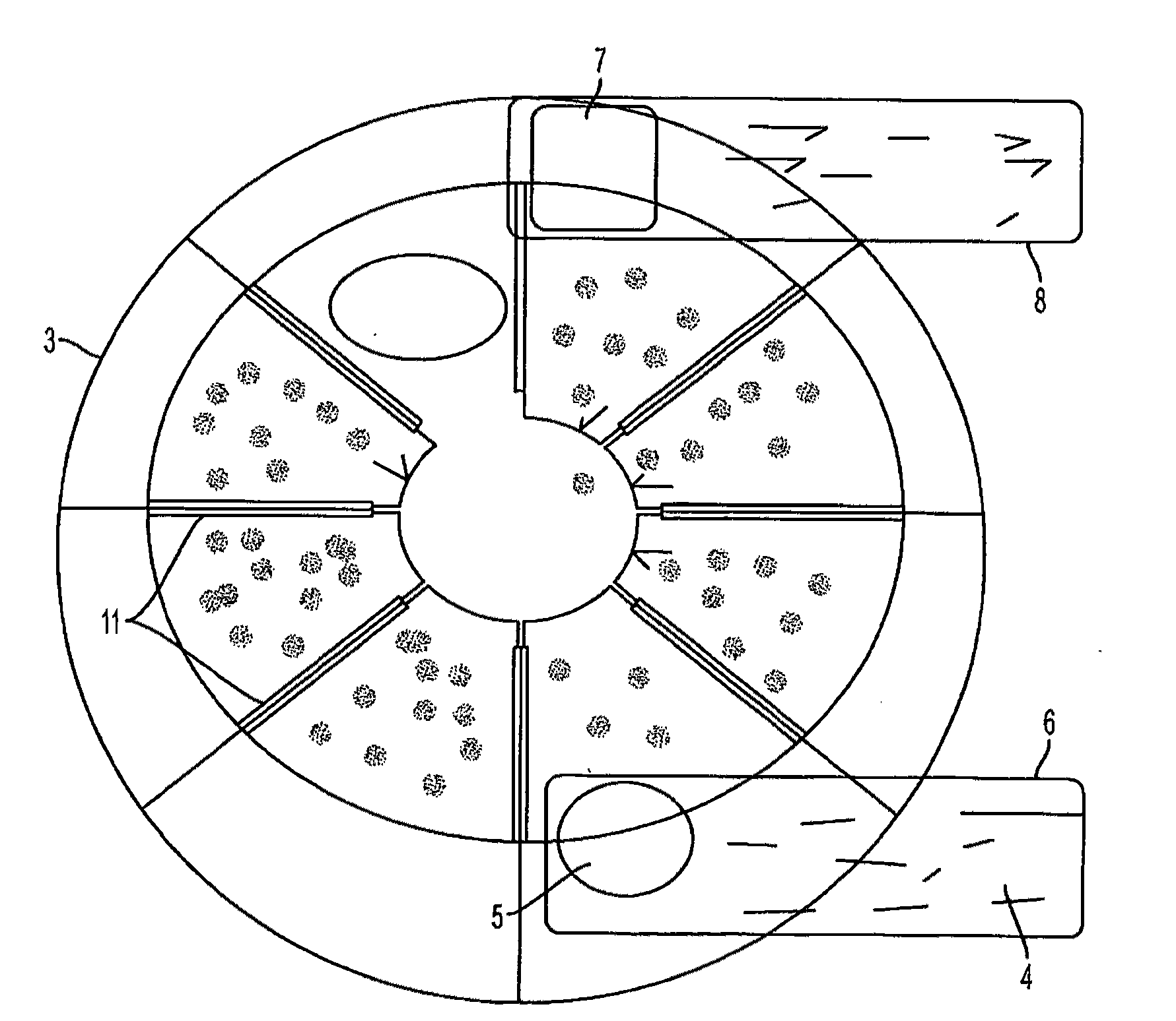
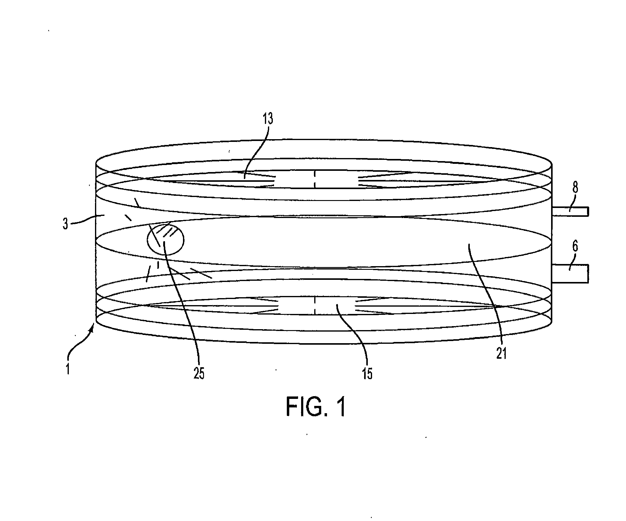
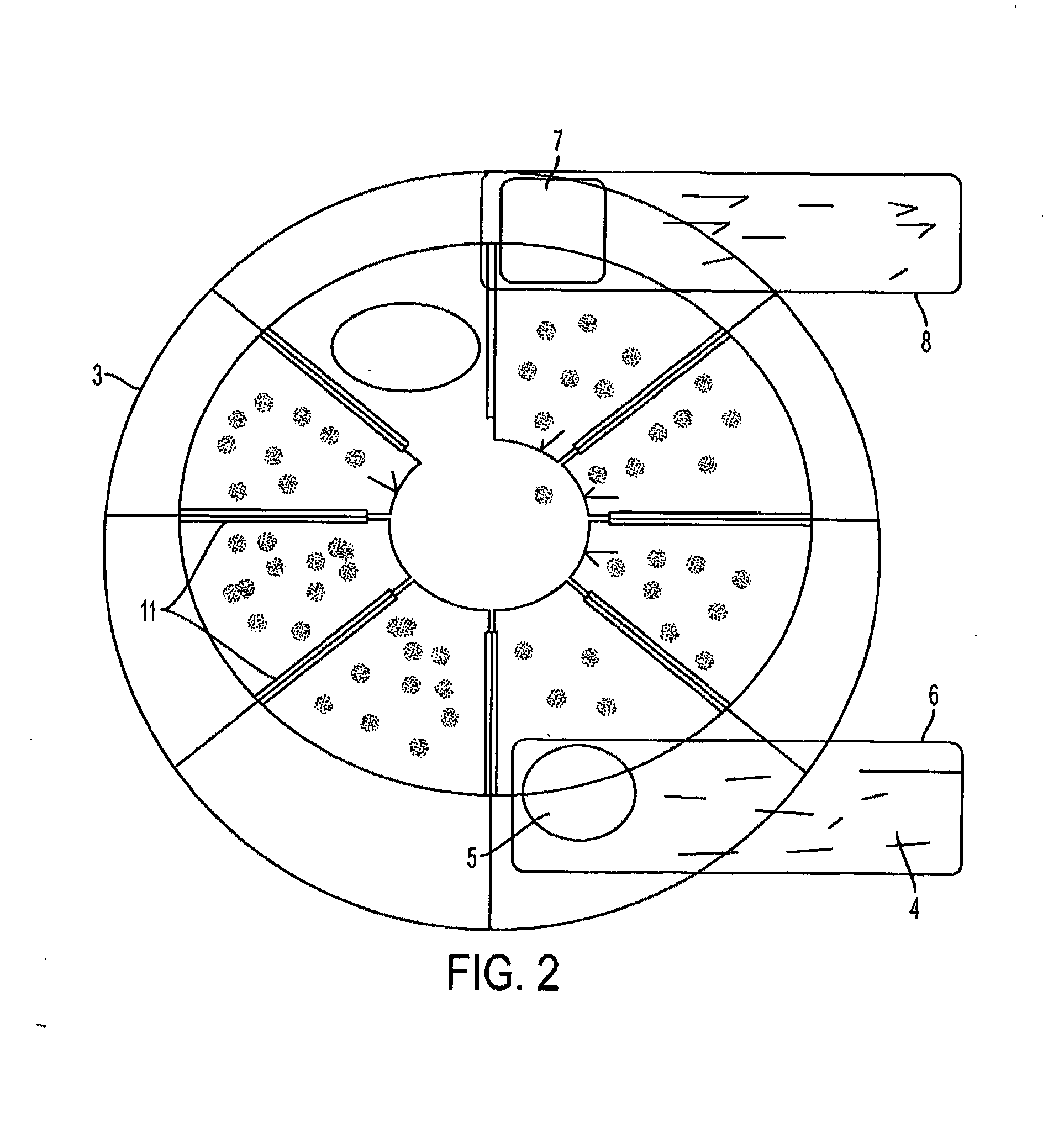
[0022]In overview of operation, as shown in FIGS. 1 to 4, the present invention comprises an electro-thermal heating system 1 comprising a substantially hollow housing 3 having detachable upper 13 and lower 15 plates for covering and sealing top and bottom surfaces of the housing 3. The housing 3 has an inlet 5 and an outlet 7 for a flow of coolant 4 to enter into and leave the housing 3, and has openings 9 defined therein, for insertion of electric heating elements 11 therein to project into the housing 3 and be in direct contact with the coolant 4 to heat it. The inlet 5 and the outlet 7 can be interconnected with piping (6,8) to form a closed fluid flow circuit. A diameter of the inlet 5 is greater than a diameter of the outlet 7, so as to to temporarily inhibit and keep coolant 4 in the housing 3 longer to heat it in a faster and more efficient manner.

[0023]Further, the housing can possess, in addition to the detachable upper 13 and lower 15 plates, one or more detachable middle...


PUM


Abstract

An electro-thermal heating system comprising a substantially hollow housing having detachable upper and lower plates for covering and sealing top and bottom surfaces of the housing. The housing has an inlet and an outlet for a flow of coolant to enter into and leave the housing, and has openings defined therein, for insertion of electric heating elements therein to project into the housing and be in direct contact with the coolant to heat it. The inlet and the outlet can be interconnected with piping to form a closed fluid flow circuit. The housing is substantially circular, to circulate flow of the coolant in a circular manner within the housing, and a diameter of the inlet is greater than a diameter of the outlet, to keep coolant in the housing longer to heat it. A pump and a power source can be interconnected to the system to circulate the coolant in the closed fluid flow circuit.

Description

[0001]This invention relates generally to a heating system, and more particularly to an improved electro-thermal heating system which is durable and reliable, that possesses easily removable or replaceable heating elements, and which can be easily installed in, for example, a home or garage.DESCRIPTION OF THE PRIOR ART[0002]It is well known that, for example, furnaces can be used to heat spaces such as homes. Traditionally, such furnaces were oil furnaces. However, as the demand for oil has risen sharply in the last decade, the price has correspondingly risen sharply, reducing the ability of such furnaces to be economical to the home or business owner. Recently, gas-fired applications, using natural gas, have been much in demand for homeowners in economically heating their home. However, much as has occurred with oil, natural gas has also seen large price increases in the last couple of years, which has also reduced the economical viability of gas-fired applications.[0003]It is also...

Claims


Application Information

Patent Timeline
Patent Type & Authority Applications(United States)
IPC IPC(8): H05B3/60
CPCF24H1/103F24H9/0015F24H3/062
Inventor KING, RAY
Owner DYNACURRENT TECH
Why Eureka
Try Eureka