
Device and method for reducing the self-interference signal in a full-duplex communication system

Active Publication Date: 2019-03-28
COMMISSARIAT A LENERGIE ATOMIQUE ET AUX ENERGIES ALTERNATIVES
View PDF0 Cites 2 Cited by
  • Summary
  • Abstract
  • Description
  • Claims
  • Application Information

AI Technical Summary

Benefits of technology

The invention aims to eliminate self-interference in a full-duplex reception signal by determining complex gains and minimizing residue signals. The method does not require clock synchronization between transmission and reception and has a minimal footprint. The technical effect of the invention is improved signal quality and better performance of wireless communication systems.

Problems solved by technology

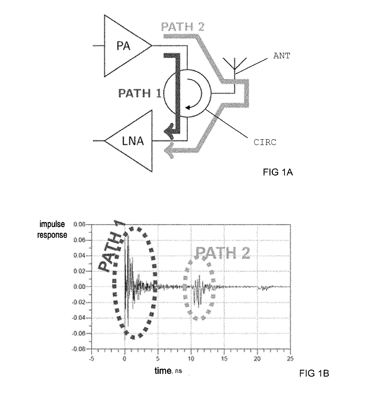
However, the main issue of the “In Band Full-duplex” technology lies in the reduction of the self-interference signal (“Self-interference cancellation”) which results from the interference between the transmission channel and the reception channel.
In this configuration, the insulation between the input and output channels can be of the order of 20 dB, which is also insufficient.
However, this solution is unsatisfactory, because the different delay lines used to apply the variable delays occupy a significant silicon surface area, which is inconsistent with the development of communication objects of small size and at low cost, such as mobile terminals.
Nor is this solution satisfactory, because it uses a clock synchronization between the transmission and reception carriers, even though the full-duplex does not require clock synchronization between transmission and reception.

Method used


Image

  • Device and method for reducing the self-interference signal in a full-duplex communication system
  • Device and method for reducing the self-interference signal in a full-duplex communication system
  • Device and method for reducing the self-interference signal in a full-duplex communication system

Examples


Embodiment Construction

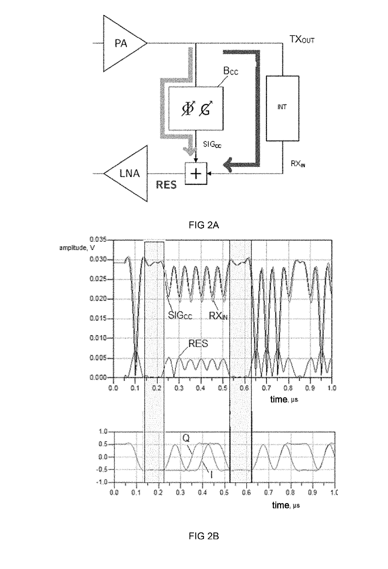
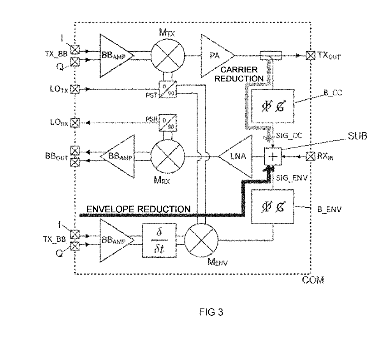
[0042]Consider FIG. 3, which schematically illustrates an architecture of the reduction device according to the invention, of a communication device COM. A baseband transmission signal TXBB comprises a component I (phase component) and a component Q (quadrature component), which can be amplified by a baseband amplifier BBAMP. One example of signals of the components I and Q is shown at the bottom of FIG. 2B. In the case of a single-carrier modulation QPSK, each component I and Q can take two states. The component I is mixed by a mixer Mix with a transmission carrier signal LOTX, and the component Q is mixed by the mixer Mix with the same transmission carrier signal LOTX (phase-shifted by 90° by the phase-shifting module PST. The sum of these two mixed signals is then amplified by an amplifier PA, and the amplified signal, designated TXOUT, is sent to an antenna interface (not represented). The reception signal RXIN contains a self-interference contribution corresponding to the trans...


PUM


Abstract

A device for reducing a self-interference contribution in a full-duplex wireless communication system configured to transmit a transmission signal and modulated by a baseband signal, and configured to receive a reception signal containing a self-interference contribution corresponding to the transmission signal, the reduction device comprising a first reduction module, configured to take a replica of the transmission signal, and configured to generate a first reduction signal, the device further comprising: a second reduction module, arranged so as to be able to take a replica of the baseband signal, and capable of generating a second reduction signal that is a function of the temporal derivative of the baseband signal, a subtractor, linked to the first reduction module and to the second reduction module, and configured to subtract from the reception signal the first reduction signal and the second reduction signal.

Description

CROSS-REFERENCE TO RELATED APPLICATIONS[0001]This application claims priority to foreign French patent application No. FR 1758937, filed on Sep. 27, 2017, the disclosure of which is incorporated by reference in its entirety.FIELD OF THE INVENTION[0002]The invention relates to a device and to a method for reducing the self-interference signal that is present in a reception signal of a full-duplex communication system.BACKGROUND[0003]Communication networks these days have to provide an increasingly higher bit rate, with an increasingly congested frequency spectrum. The conventional telecommunication methods rely on a so-called half-duplex technology, in which the transmitter and the receiver communicate alternately (Time Division Duplexing) or on different frequency bands (Frequency Division Duplexing).[0004]The so-called in band full-duplex (IBFD) technology relies on the principle of transmission and reception at the same time and on the same frequency band, which theoretically make...

Claims


Application Information

Patent Timeline
IPC IPC(8): H04B1/525H04B1/56H04B1/12H04B15/00H04B1/04
CPCH04B1/525H04B1/56H04B1/126H04B15/00H04B1/0475H04B1/10H04B1/123H04B3/23H04B3/232H04B15/04H04L5/1461
Inventor GRAVE, BAPTISTEGIRY, ALEXANDRE
Owner COMMISSARIAT A LENERGIE ATOMIQUE ET AUX ENERGIES ALTERNATIVES
Learn More