Vertical Underground Storage Tank and Method of Installing and Forming the Same
a vertical underground storage and tank technology, applied in water conservation, transportation and packaging, sewage draining, etc., can solve the problems of large footprint, limited installation, time and cost, and large planning,
- Summary
- Abstract
- Description
- Claims
- Application Information
AI Technical Summary
Benefits of technology
Problems solved by technology
Method used
Image
Examples
embodiment 100
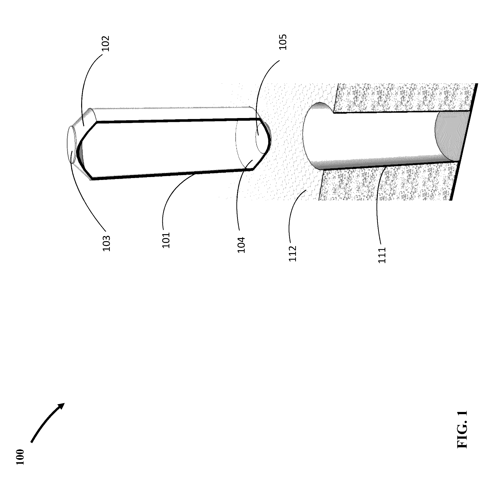
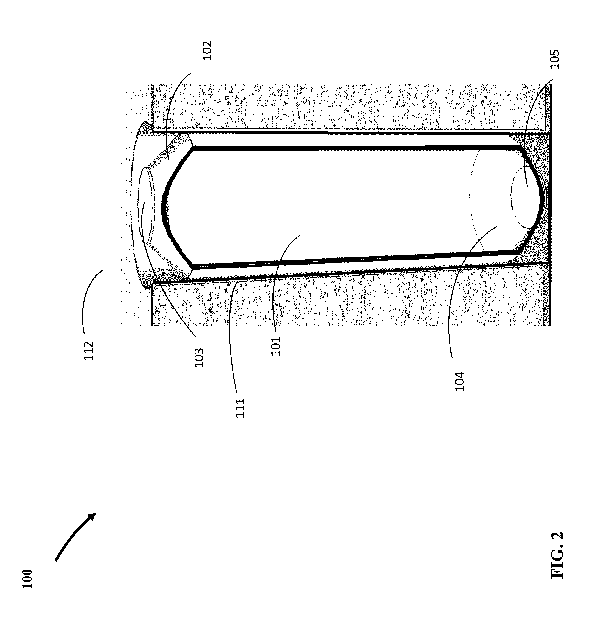
[0032]FIG. 2 is a cut section of the same embodiment 100 of the present invention as in FIG. 1. Vertical cylinder vessel 101 is placed inside vertical bored underground shaft 111 of marginally larger diameter and roughly the same depth below ground 112 as the length of the vessel 101. Vessel 101 is supported level in vertical position on its bottom 105 with access hatch 103 at roughly the same elevation as the ground 112, leaving a roughly uniform annular space between the vessel 101 and the shaft 111.
[0033]FIG. 3 is a cut section of the same embodiment 100 of the present invention as in FIG. 2. Vertical underground storage tank 100 is comprised of a composite of inner vessel 101 and outer concrete shell 121 installed and formed in position underground inside vertical shaft 111. Tank 100 has an access hatch 103 at the top flush with ground 112. The volume of soil removed to accommodate tank 100 equals is the gross volume of the tank 100 meaning that excavation is minimized. Also, th...
embodiment 200
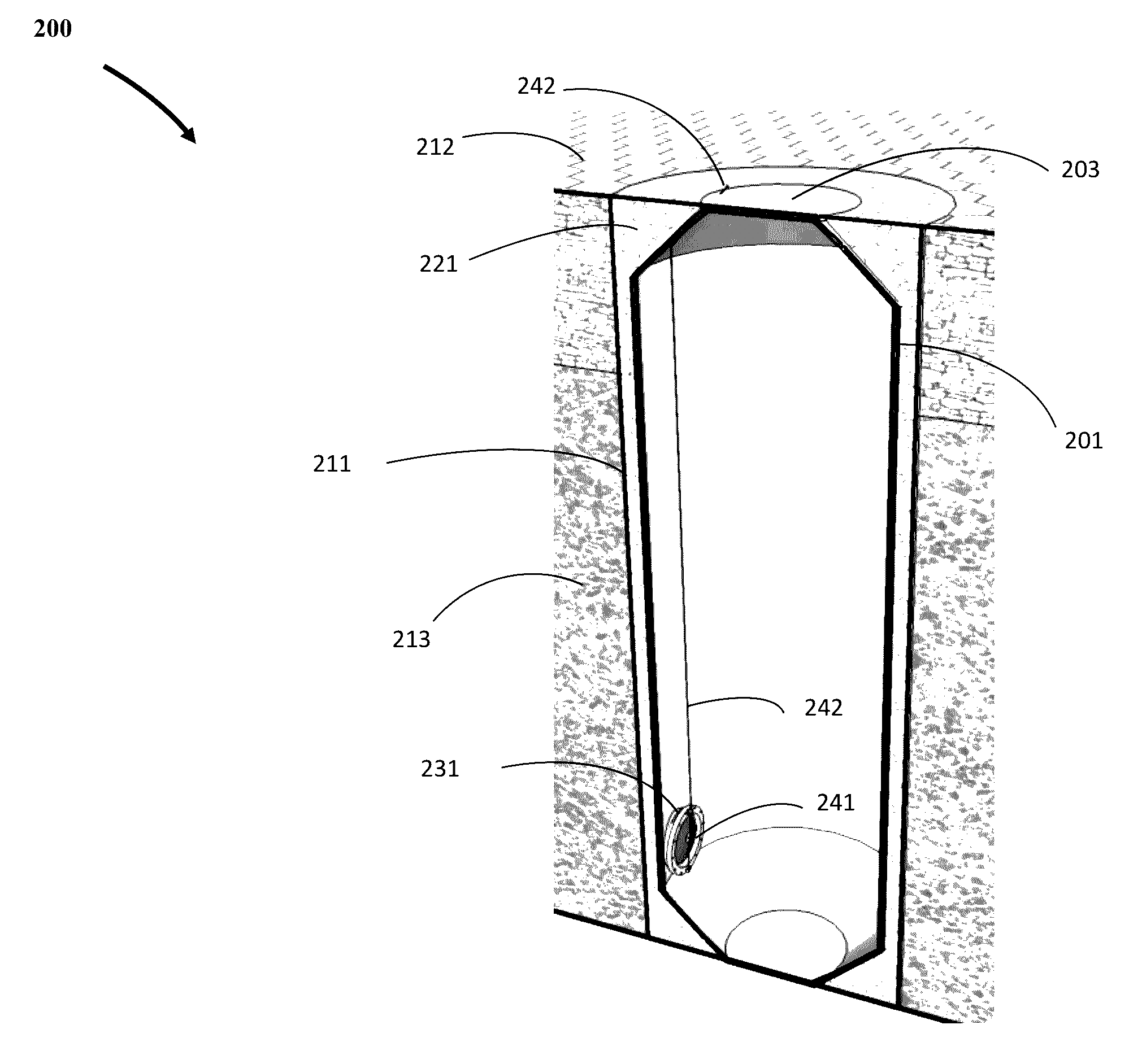
[0035]FIG. 5 is a cut section through the vessel of the same embodiment 200 of the present invention as in FIG. 4. Port 231 above transition 204 to bottom 205 of vessel 201 is equipped with inflatable plug 241 that serves as the open / close device for port 231. Inflatable plug 241 is in uninflated “open” position during installation and can be inflated to “closed” position by air tube that leads to outside of vessel 201.
[0036]FIG. 6 is a cut section through the same embodiment 200 of the present invention as in FIG. 4. Vertical cylinder vessel 201 is inserted inside bored shaft 211 while port 231 shown in FIG. 5 is “open” allowing groundwater 213 to enter inside vessel 201. Air tube 242 extends outside vessel 201 and is pressurized to close inflatable plug 241 shown in FIG. 5 once vessel 201 is in position. Vessel 201 is supported in level vertical position on its bottom 205 shown in FIG. 5 with access hatch 203 at roughly the same elevation as the ground 212, leaving a roughly unifo...
embodiment 300
[0041]FIG. 11 is a cut section through the same embodiment 300 of the present invention as in FIG. 10. Both the first vertical cylinder vessel 301 and the second vertical cylinder vessel 302 are inside their respective bored vertical shafts 311 and 302, with their connection flanges 331 and 331 aligned.
[0042]FIG. 12 is a cut section through the same embodiment 300 of the present invention as in FIG. 10. There is a horizontal underground boring 351 between the connection flanges 331 and 332 of the two vertical cylinder vessels 301 and 302 inside their corresponding bored underground shafts 311 and 312. Horizontal underground boring techniques is used for trenchless pipe laying in water, sewer, and gas pipeline industries and is widely available.
[0043]FIG. 13 is a cut section through the same embodiment 300 of the present invention as in FIG. 10. There is a pipe sleeve 352 inserted in the horizontal boring 351 shown in FIG. 12 between the connection flanges 331 and 332 of the two vert...
PUM
 Abstract
Description
Claims
Application Information
 - R&D
- Intellectual Property
- Life Sciences
- Materials
- Tech Scout
- Unparalleled Data Quality
- Higher Quality Content
- 60% Fewer Hallucinations
Browse by: Latest US Patents, China's latest patents, Technical Efficacy Thesaurus, Application Domain, Technology Topic, Popular Technical Reports.
© 2025 PatSnap. All rights reserved.Legal|Privacy policy|Modern Slavery Act Transparency Statement|Sitemap|About US| Contact US: help@patsnap.com


