Apparatus for pressurized conveyance in gravity conduits

Active Publication Date: 2016-10-06
EFTEKHARZADEH SHAHRIAR
View PDF7 Cites 0 Cited by
  • Summary
  • Abstract
  • Description
  • Claims
  • Application Information

AI Technical Summary

Benefits of technology

[0008]The collapsible pipe has similar properties to commonly available lay-flat pipes used in fire-fighting and in irrigation. Its lay-flat property allows it to occupy negligible space in the gravity conduit headspace when the headspace is needed for gravity conveyance, and only assumes its circular shape when there is no gravity flow in the headspace. The collapsible pipe of the present invention is equipped with a combined anchorage and segregation system that make

Problems solved by technology

Therefore, the full conveyance capacity of gravity pipes is grossly underutilized.
Given the increase in water conservation, the flow rates and depths in gravity conduits are decreasing making them increasingly more underutilized.
Many cities are embarking on extensive and costly pipeline construction projects

Method used


Image

  • Apparatus for pressurized conveyance in gravity conduits
  • Apparatus for pressurized conveyance in gravity conduits
  • Apparatus for pressurized conveyance in gravity conduits

Examples


Embodiment Construction

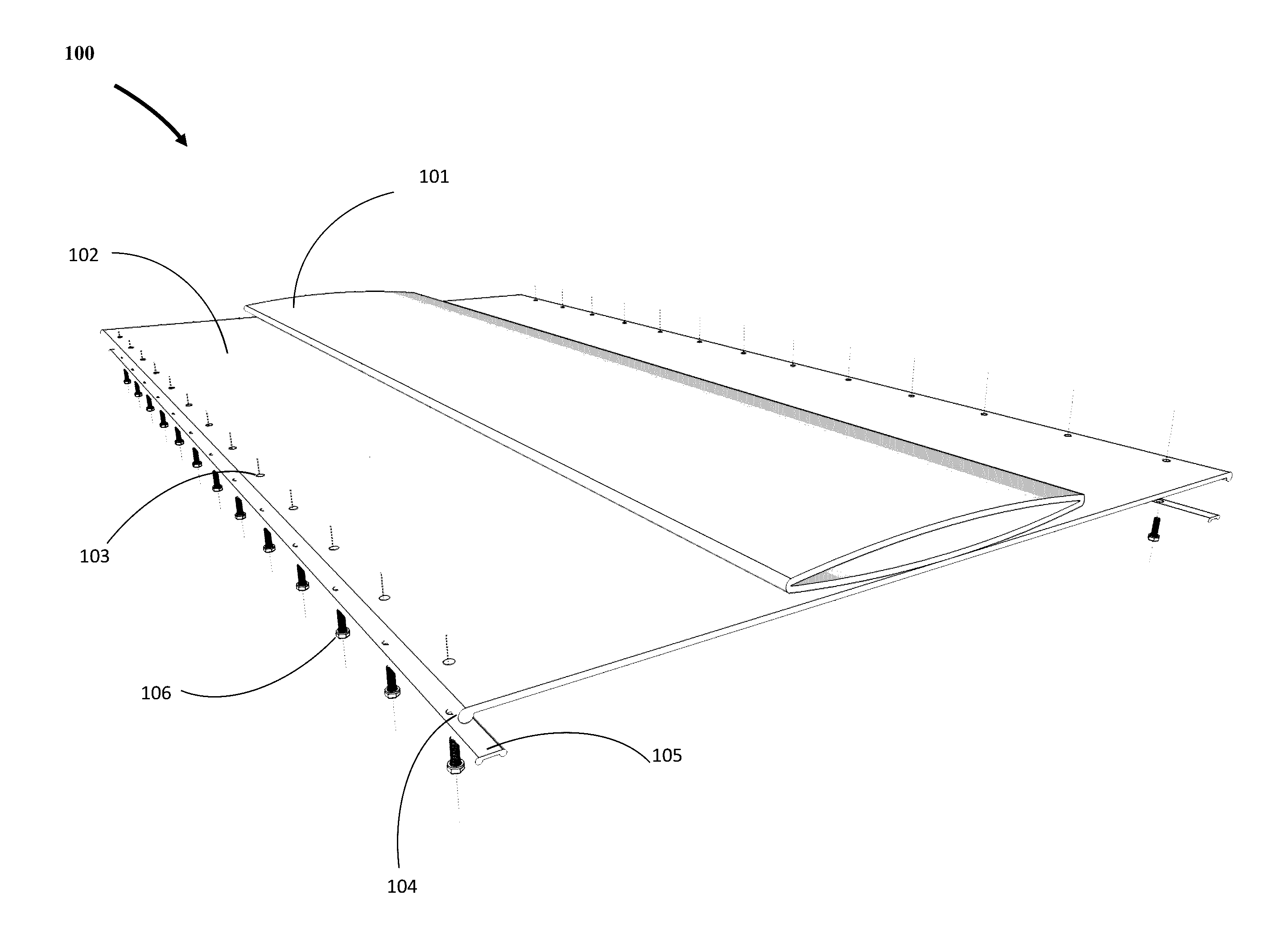
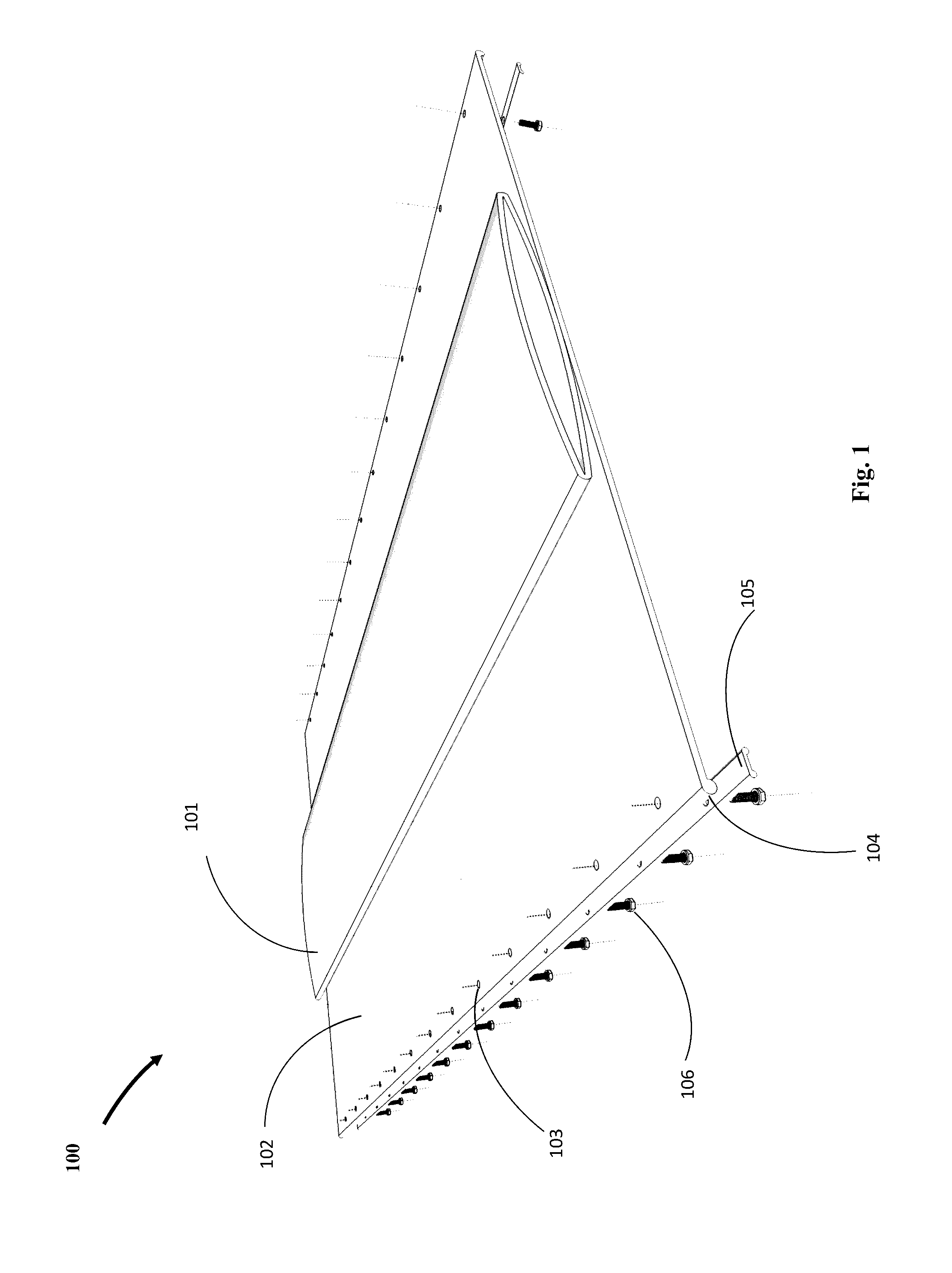
[0017]Referring to FIG. 1, there is shown the perspective view of one embodiment of the invention 100 comprised of collapsible lay-flat pipe 101, which is attached along its underside to a flat sheet of flexible and impermeable fabric 102 using appropriate adhesive (not shown) along the centerline over a certain width. The fabric 102 has equally spaced anchor holes 103 on its sides and may have thicker round edges 104 to guard against slippage when anchored. Also shown is anchor plate 105 with equally spaced anchor holes that coincide with anchor holes 103 on the fabric 102, each of which fits an anchor bolt 106.

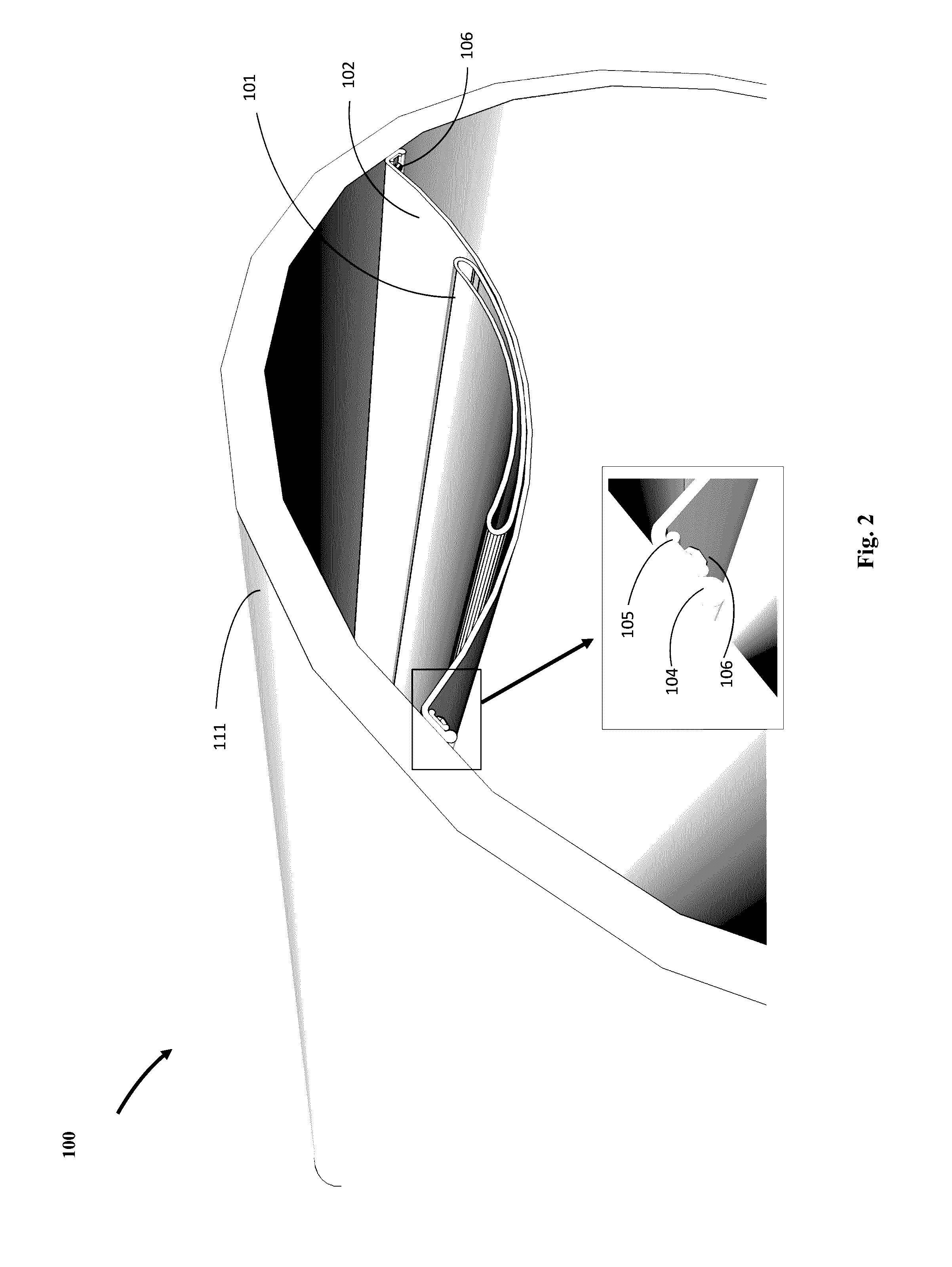
[0018]FIG. 2 is a perspective view of the embodiment of the present invention shown in FIG. 1 installed inside a gravity pipe 111. The anchor bolts 106 are firmly secured to the inside of the gravity pipe 111 through the anchor plate 105 and the fabric 102. Correctly sized and spaced holes along two predetermined alignments inside the gravity 111 on opposite sides may be dri...


PUM


Abstract

An apparatus for increasing the utility of gravity conduits by using their underutilized headspace for pressurized conveyance.

Description

FIELD OF THE INVENTION[0001]The present invention is in the field of devices for conveyance of fluids. More specifically, the present invention relates to increasing the utility of gravity conduits by using their underutilized headspace for pressurized conveyance.BACKGROUND OF THE INVENTION[0002]Gravity conduits in urban settings are widely used for conveyance of sewage and stormwater. They are designed to convey the peak flow rate under partially full flow conditions, while the actual day-to-day flow rate and depth of flow are substantially less.[0003]Separate sanitary sewers experience daily peak flows during the hours of maximum water use and are designed to convey the peak flow at 50% to 85% of full flow depth. Separate sanitary sewers may also receive infiltration inflows from surrounding groundwater and during wet-weather conditions, which are accommodated for in the design to ensure partially full flow conditions during peak flows. Storm drains that collect wet-weather flows ...

Claims


Application Information

Patent Timeline
IPC IPC(8): E03F3/04F16L9/14
CPCF16L9/14E03F3/043F16L9/19
Inventor EFTEKHARZADEH, SHAHRIAR
Owner EFTEKHARZADEH SHAHRIAR
Why Eureka
Try Eureka