Eureka AIR delivers breakthrough ideas for toughest innovation challenges, trusted by R&D personnel around the world.

Color print module for a franking machine

a module and franking machine technology, applied in the field of mail handling, can solve the problems of increasing the overall length of the machine in which the module is incorporated, unable to obtain the fluorescent red needed for printing franking marks, and difficulty in obtaining satisfactory franking marks beyond a certain printing speed, so as to achieve the effect of not adversely affecting the printing speed

Inactive Publication Date: 2012-06-07
NEOPOST TECH SA
View PDF21 Cites 2 Cited by
  • Summary
  • Abstract
  • Description
  • Claims
  • Application Information

AI Technical Summary

Benefits of technology

"The present invention relates to a color franking machine that can print a franking mark on a mailpiece using at least three primary inks, namely cyan, magenta, and yellow, and can also use the same set of primary inks for printing other graphical elements, such as logos, advertisements, and images. The invention solves the problem of difficulty in obtaining satisfactory franking marks beyond a certain printing speed, which is typically 1 meter per second, by providing a method for printing the franking mark using a combination of inks that can be used with a conventional three- or four-print head. The invention also allows for the use of a single set of primary inks for printing both in countries that require red postal ink and in countries that require blue postal ink. The invention is cost-compatable and can be used in franking machines having current architectures without requiring significant alteration to its software configuration."

Problems solved by technology

Unfortunately, franking marks must comply with postal specifications such as those defined, for example, in Universal Postal Union (UPU) Standard S44, in particular in terms of contrast and of modulation for reading bar codes and, in practice, it is very difficult to obtain satisfactory franking marks beyond a certain printing speed that is typically 1 meter per second (m / s) with a combination of inks.
The positioning errors in the ink droplets coming from different heads perturb reading bar codes, even when such errors are hardly discernable with the naked eye.
In addition, even with such an extended gamut of colors, it is not possible to obtain the fluorescent red necessary for printing franking marks in the USA or in Canada.
Unfortunately, it is very costly due to adding the color print module in addition to the standard postal print module, and that addition also increases the overall length of the machine in which the module is incorporated and significantly alters its architecture.

Method used


Image

  • Color print module for a franking machine
  • Color print module for a franking machine
  • Color print module for a franking machine

Examples


Embodiment Construction

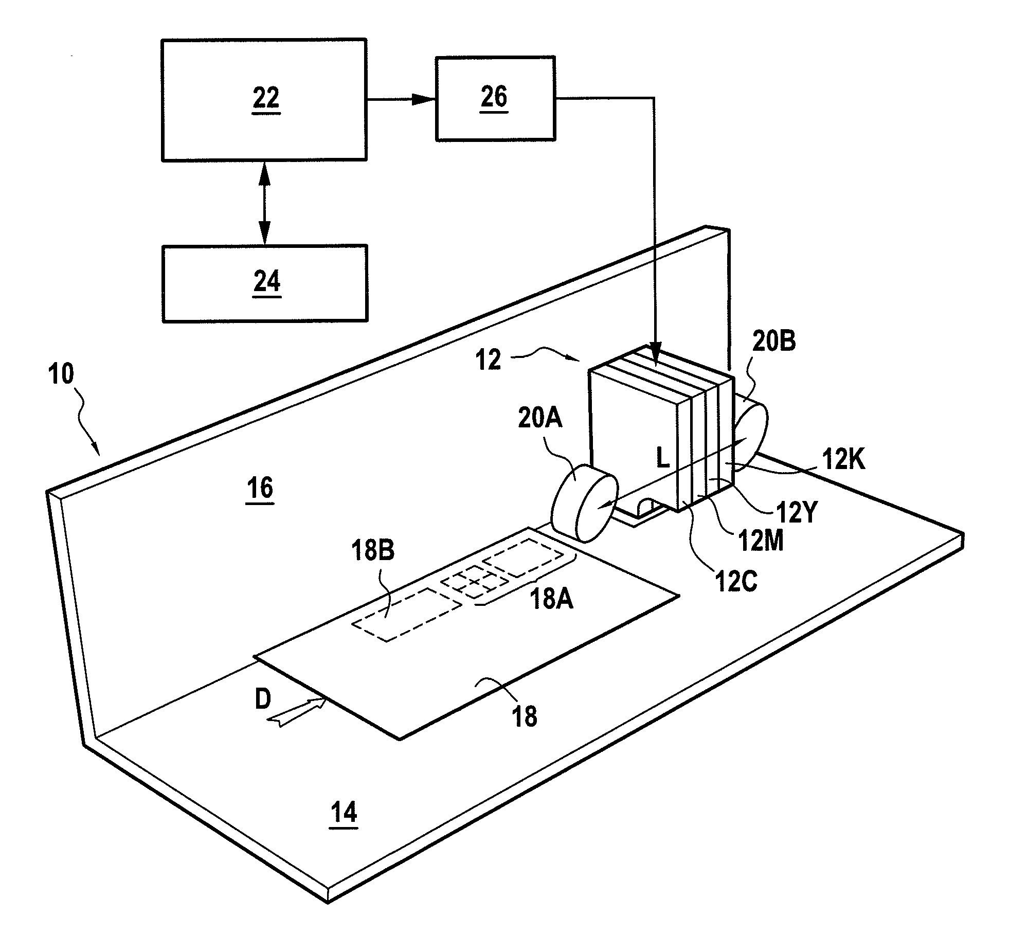
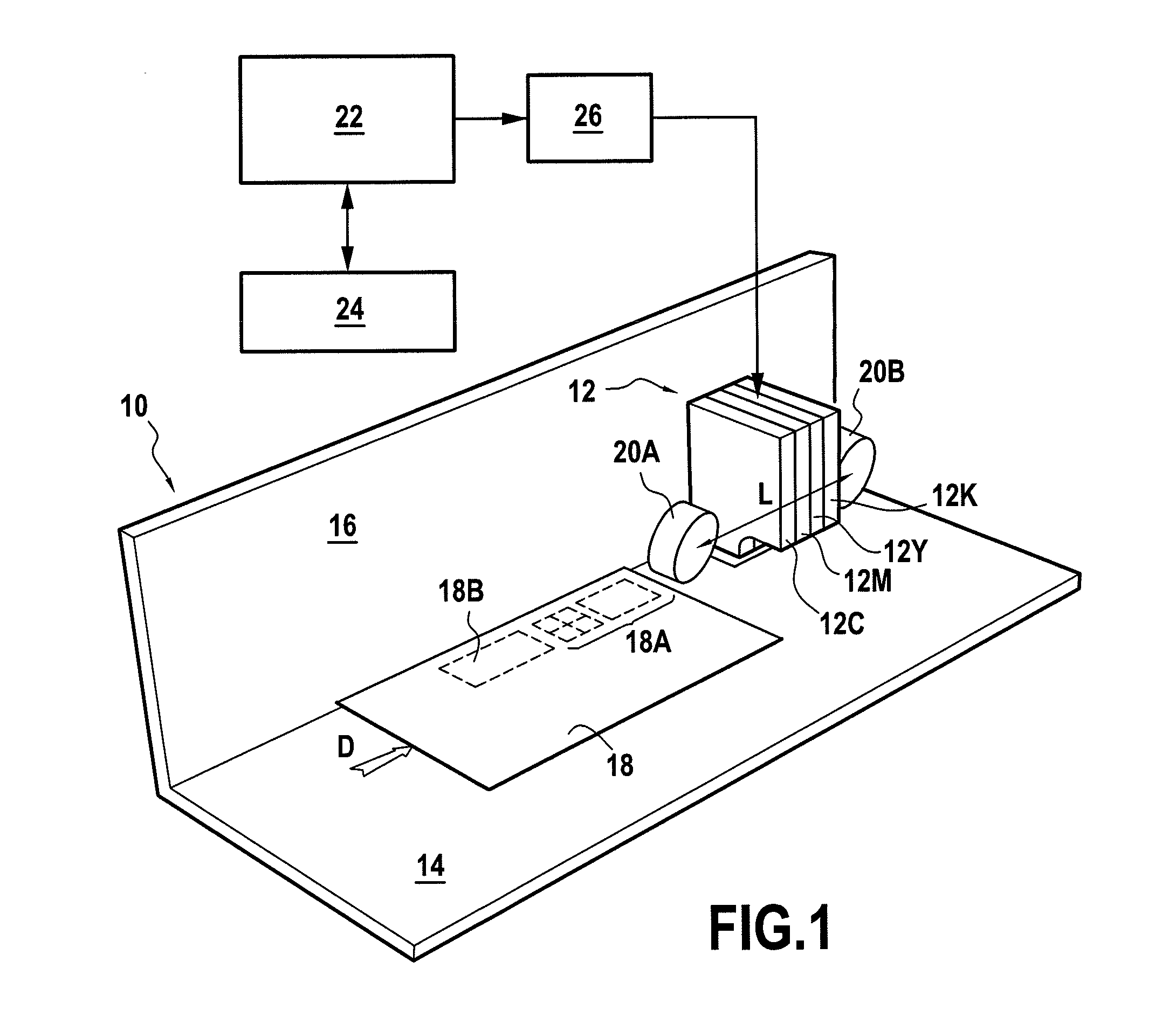
[0020]FIG. 1 is a fragmentary diagrammatic view of an inkjet franking machine 10 with its print head 12 overlying a guide plate 14 on which mailpieces 18 are conveyed in a longitudinal movement direction D and are jogged against a referencing wall 16. Said mailpieces are conveyed, as is known, by rollers (only the counter-rollers 20A, 20B are shown, which counter-rollers are disposed above the guide plate 14 immediately upstream and immediately downstream from the print head 12, and define between them a minimum printing length for printing the mailpieces) or by conveyor belts of the franking machine, in such a manner as to pass under the print head, thereby making it possible to print a postal imprint 18A on each of said mailpieces. Naturally, as in any franking machine, control circuits (not shown) are provided in its base so as to operate it and in particular so as to rotate the conveyor rollers depending on the positions of the mailpieces as they go through the machine as sensed...


PUM


Abstract

A color printing method for a franking system making it possible to print a franking mark on a mailpiece using at least three primary inks, namely cyan, magenta, and yellow, wherein at least one of said primary inks, namely cyan or magenta, is constituted by a similar postal ink, namely postal blue for cyan and / or postal red for magenta.

Description

FIELD OF THE INVENTION[0001]The present invention relates to the field of mail-handling, and in particular to the field of franking machines or “postage meters”, or of other envelope printers, each of which includes an inkjet digital print module.PRIOR ART[0002]Nowadays, inkjet printing is in very widespread use for printing photographs, and office documents, but, over the last ten years or so, it has also been used in the postal field for printing franking or “postage” marks. For such postal use, printing is then monochrome only, and of a specific color or “postal color” that varies depending on the country of franking (fluorescent red for the USA and Canada, 185U red in Great Britain, and postal blue for Germany and France, for example), and printing is then both of the franking mark proper and of any logos, adverts, images, or messages that might accompany it.[0003]If the sender then wishes the graphical elements other than the franking mark not to be printed in the same color as...

Claims


Application Information

Patent Timeline
Patent Type & Authority Applications(United States)
IPC IPC(8): B41F3/44B41M1/14
CPCG07B17/00508G07B2017/00532G07B2017/00653
Inventor PILLARD, ROMAIN
Owner NEOPOST TECH SA
Why Eureka
Eureka Blog
Learn More