Apparatus and Method for Installing Utility Service Lines in Road Pavements

a technology for installing utility service lines and trenches, which is applied in the direction of cables, cable installation in underground tubes, apparatus for laying cables, etc., can solve the problems of gross underutilization of resources, difficult to achieve new alignments and construction of new utility service lines in urban areas, and utility lines permitted within. , to achieve the effect of increasing the utilization of roads and ensuring the stability and longevity of trenches

Inactive Publication Date: 2016-11-17
EFTEKHARZADEH SHAHRIAR
View PDF9 Cites 1 Cited by
  • Summary
  • Abstract
  • Description
  • Claims
  • Application Information

AI Technical Summary

Benefits of technology

[0007]One key advantage of the present invention is that it does not need a minimum cover depth to withstand direct traffic loads and thus allows the pipeline to be placed within the pavement with only the surface course as the cover. Another key advantage of the preset invention is that the pipeline is suspended in the trench and not directly supported by the ground meaning that there are no external forces on the pipeline that could threaten its integrity and safety.
[0008]Installation of the present invention is relatively simple and straightforward, particularly compared with existing pipes that require bed preparation, compaction, and backfill soil cover. The apparatus of the present invention is assembled by strapping bell-end pipe segments to corresponding steel plates that are shorter by the length of the spigot. In existing roads, a “T” section trench is excavated in the pavement to accommodate the plurality of steel plates and corresponding strapped pipes. The plates are then sequentially placed in the trench with the bell end facing the spigot. In plastic pipes, jointing compound is applied and the plates are sequentially pulled in to close the gap between consecutive plates and thereby fully insert the spigot into the bell until the plate ends are touching. In steel pipes that require the clamping of the bell and spigot joint, a certain length of the steel plate directly above the joint on either the bell end, the spigot end, or both may be made removable to permit the clamping operation. The installation does not require any bed preparation, backfilling, compaction, etc. of the trench as the pipe is suspended. The void space in the trench may be injected with grout through holes in the plate segments to insure the stability and longevity of the trench and not for load transfer or bearing purposes. In new road construction, the “T” section trench may be molded in the road pavement using formwork.
[0009]The present invention can be utilized in a number of embodiments that vary the number, material, and duty of the pipelines placed in the trench. The present invention allows more than one pipeline suspended from the steel plate and a combination of utility service pipes, from pressurized conveyance to cables in conduits. The present invention can be utilized as a single-line pressure pipe of certain diameter conveying a certain pressurized fluid, a multi-line pressure pipe that conveys one or a plurality of different-type fluids, a single or multi-line conduit for various-type cables, or a multi-conduit utility trench for various service lines
[0010]It is an object of the present invention to provides a technique for installing pipelines and conduits within road pavements to provide for increased utilization of the road to accommodate utility service lines.
[0011]It is an object of this invention to provide improved elements and arrangements by apparatus for the purposes described thereof, which is comparable in cost with existing systems, dependable, and fully effective in accomplishing its intended purposes.
[0012]These and other objects of the present invention will become readily apparent upon further review of the following specification and drawings.

Problems solved by technology

Increasingly, the possibility of two or more utility lines conflicting or intersecting is a problem as the need for services grow and the space underneath roads becomes congested, making the availability of new alignments and construction of new utility service lines difficult in urban areas.
There are currently no utility lines permitted within the road pavement for concern of adverse impact on the safety, integrity, construction, operation, and maintenance of public roads by transportation authorities.
The vertical space beneath the road surface that is the pavement is currently only utilized for bearing and transfer of the traffic load above to the natural ground formation below and as such is a grossly underutilized resource.
The road pavement is currently only used to accommodate utility service line in special circumstances such as road crossings by means of encasement of commercial pipe in reinforced concrete, a method not suitable for long pipelines because of several limitations including small pipe size, extensive volume of steel and concrete, long schedule, and cost.
Currently, there are no feasible techniques for constructing pipelines within the road pavement with minimal or no cover depth.

Method used


Image

  • Apparatus and Method for Installing Utility Service Lines in Road Pavements
  • Apparatus and Method for Installing Utility Service Lines in Road Pavements
  • Apparatus and Method for Installing Utility Service Lines in Road Pavements

Examples


Embodiment Construction

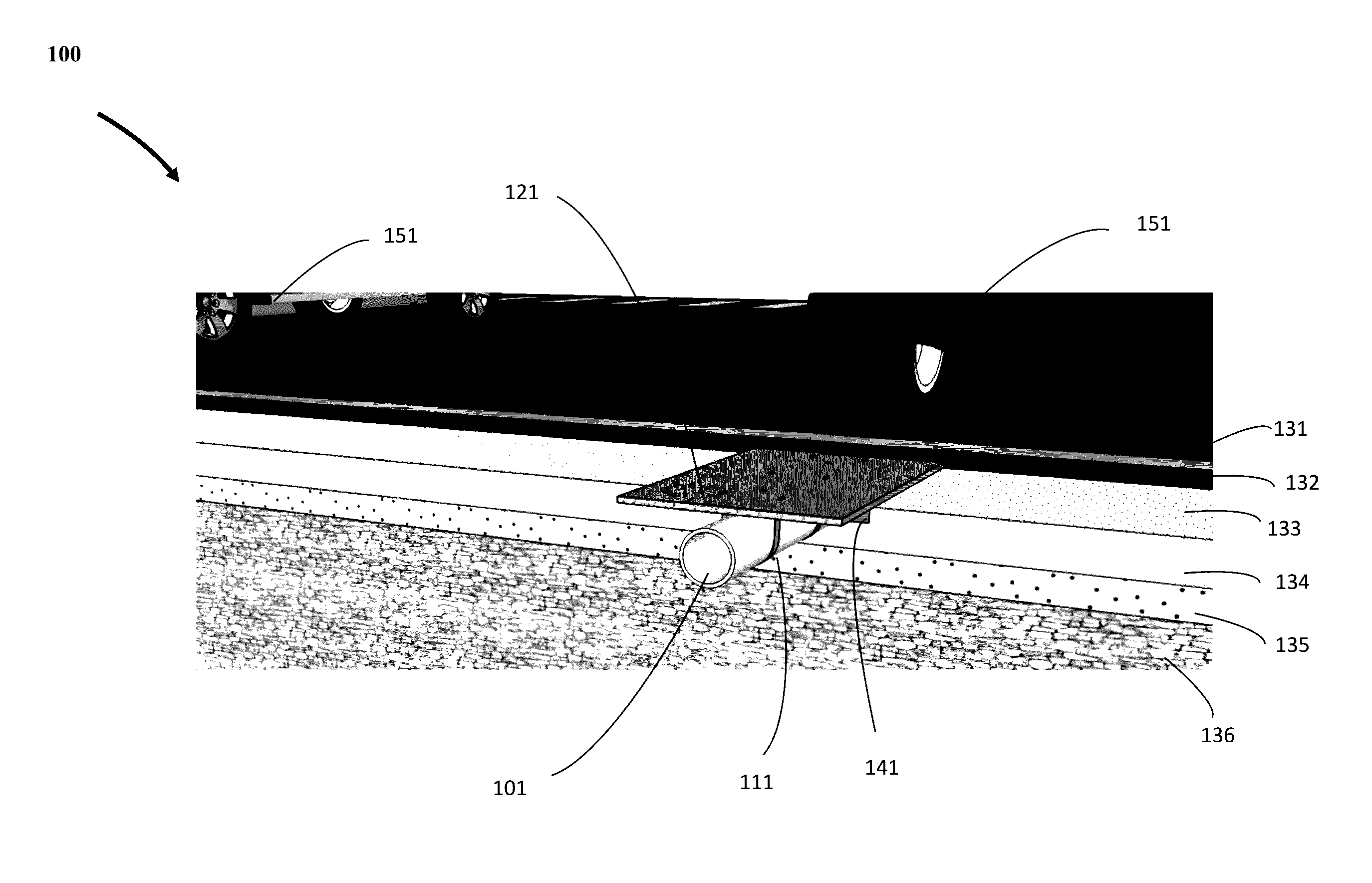
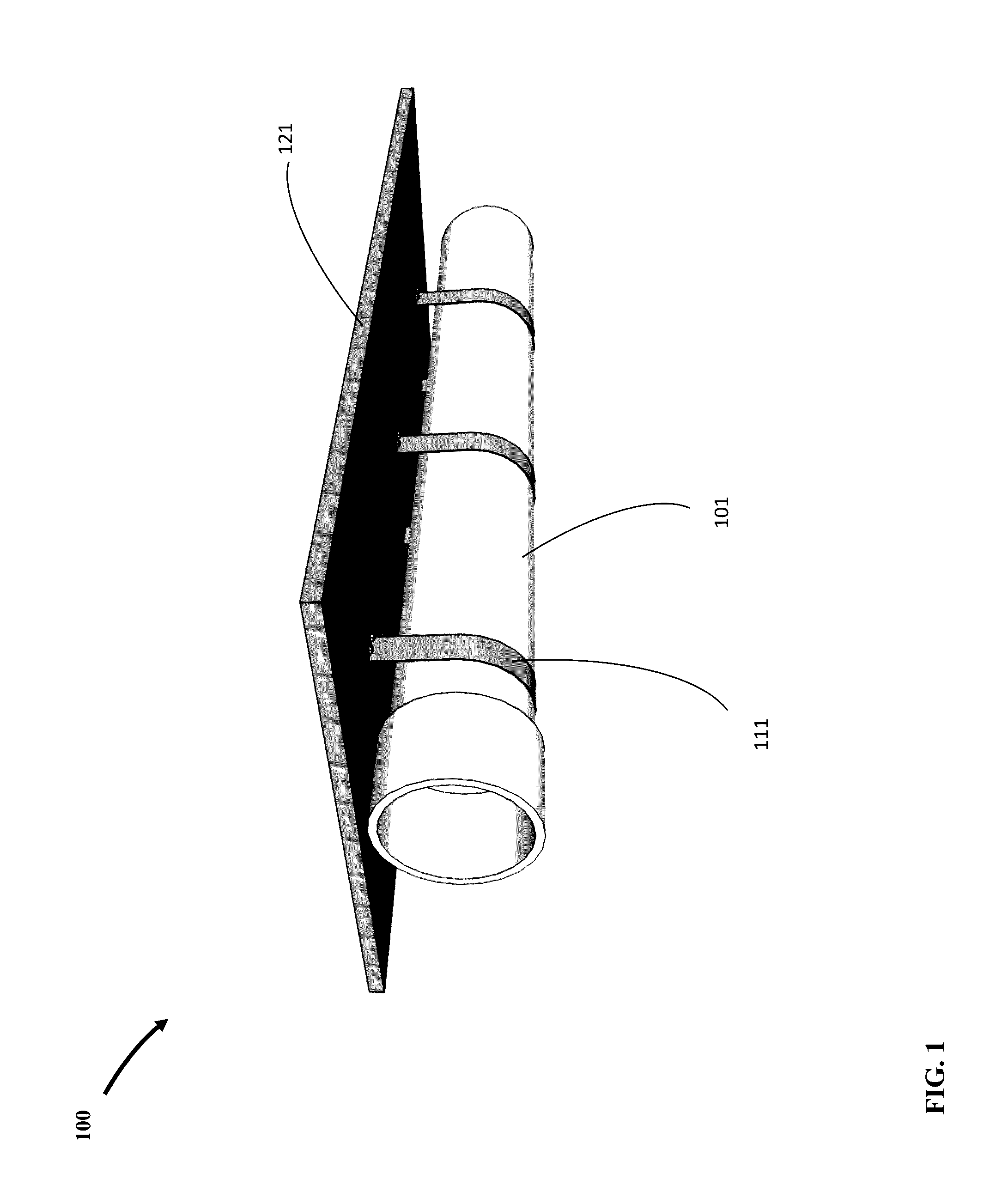
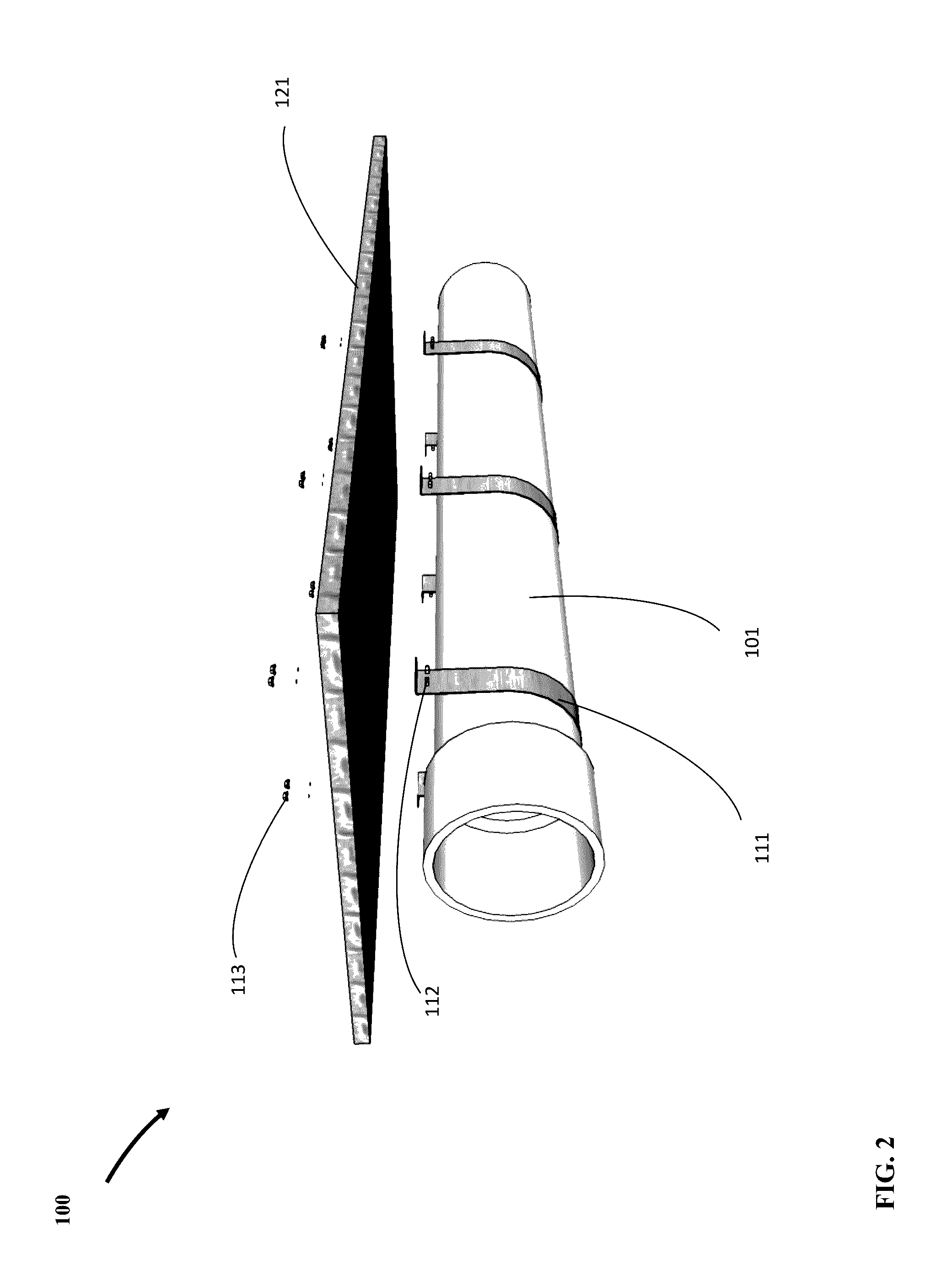
[0024]Referring to FIG. 1 there is shown an underside view of a single unit of the present invention 100 showing pipe segment 101 attached to the underside of steel plate 121 by means of straps 111 of required width, strength, and durability. Steel plate 121 is of the type suitable for covering over utility trenches in road ways and is specified and dimensioned accordingly. Pipe 101 may be made of plastic, steel, or other materials and may be purposed for conveyance of pressurized fluids and gasses, or for use as conduit for tubes and cables. Straps 111 function to support the weight of pipe 101 and transfer it to the steel plate 121, and may take different shapes and forms, made from metal in the form of a “U” clamp as shown in FIG. 2, in which case they may be fastened to the steel plate 121 with bolts 113 and nuts 112 or flexible high tensile strength plastic straps used in the art to secure loads on transportation trucks.

[0025]FIG. 3 is a top view of a single unit of the present...


PUM


Abstract

An apparatus and a method for installing pipes and conduits in road pavements with minimum cover.

Description

FIELD OF THE INVENTION[0001]The present invention pertains to utility service lines within the right-of-way of public roads and streets. More specifically, the present invention provides an apparatus and a method for installing pipes and conduits in road pavements with minimum cover.BACKGROUND OF THE INVENTION[0002]Transportation, communications, and utility networks are essential components of modern life. A major part of such networks are pipelines and cables that run below the surface mostly in the right-of-way of public roads and streets. Increasingly, the possibility of two or more utility lines conflicting or intersecting is a problem as the need for services grow and the space underneath roads becomes congested, making the availability of new alignments and construction of new utility service lines difficult in urban areas. Utility service lines take the form of a conduit or pipeline, which are herein used interchangeably with utility service lines to mean the same.[0003]Curr...

Claims


Application Information

Patent Timeline
Patent Type & Authority Applications(United States)
IPC IPC(8): E01C9/00E01C1/00F16L1/06F16L3/14E01F5/00F16L1/032
CPCE01C9/002E01F5/005F16L1/032E01C2201/00F16L3/14E01C1/00E01C9/001F16L1/06F16L1/028F16L3/133H02G1/06H02G9/06
Inventor EFTEKHARZADEH, SHAHRIAR
Owner EFTEKHARZADEH SHAHRIAR
Why Eureka
Try Eureka