Copper clad ballast wire

a ballast wire and copper technology, applied in the direction of reducing the size of cables/conductors, conductors, lighting and heating apparatus, etc., can solve the problems of significant safety and reliability problems, heavy weight, and wires that could be broken, so as to save material costs, eliminate the waste of excessive pure copper, and carry up safely

Inactive Publication Date: 2008-08-21
YANG KEVIN
View PDF9 Cites 3 Cited by
  • Summary
  • Abstract
  • Description
  • Claims
  • Application Information

AI Technical Summary

Benefits of technology

[0012]The present invention provides a novel ballast lead wire, which is capable of safely carrying up to 2 amperes of electronic current. Specifically, the present invention uses as the core for ballast lead wire either a copper-clad iron including steel or copper-clad aluminum, which could be one of copper-clad conductors of any other alloys to save the cost of material such as copper. Copper clad iron and copper clad aluminum can be as mechanically strong as copper. Copper clad over lower cost metal can take the advantage of the electrical conductivity of copper and its soldering-ability while eliminating the waste of using excessive pure copper. The substituted metal material, of course, should be much cheaper than copper. Thus, it is one of effective ways to reduce ballast's material cost.
[0013]The lead wire may have a larger diameter for a comparable cost resulting in more energy efficient wiring of the space or the whole building system. In fact, for metal wire, the larger the diameter of the wire the lower the electrical resistance by the wire meaning corresponding reduction of wasted energy by the circuit. Lighting systems typically consist of permanently wired-in lighting fixtures, with each lighting fixture obtaining its power directly from a regular Class 1 power line.

Problems solved by technology

The reasons for the mandatory use of the gauge #18 wires for all ballast's lead wire is as follows:(1) In the past, most US standard electrical-magnetic ballast were made of a bundle of steel laminations combined with heavy copper coils, and they are bulky and very heavy.
People sometimes need to hold the ballast by the lead wire to move it from one place to another, and the lead wire could be broken if it was not mechanically strong enough.
These handy locking connections could result in bad connections if less than #18 gauge wires were used, and as the direct consequences it could create significant safety and reliability issues.

Method used


Image

  • Copper clad ballast wire
  • Copper clad ballast wire
  • Copper clad ballast wire

Examples


Embodiment Construction

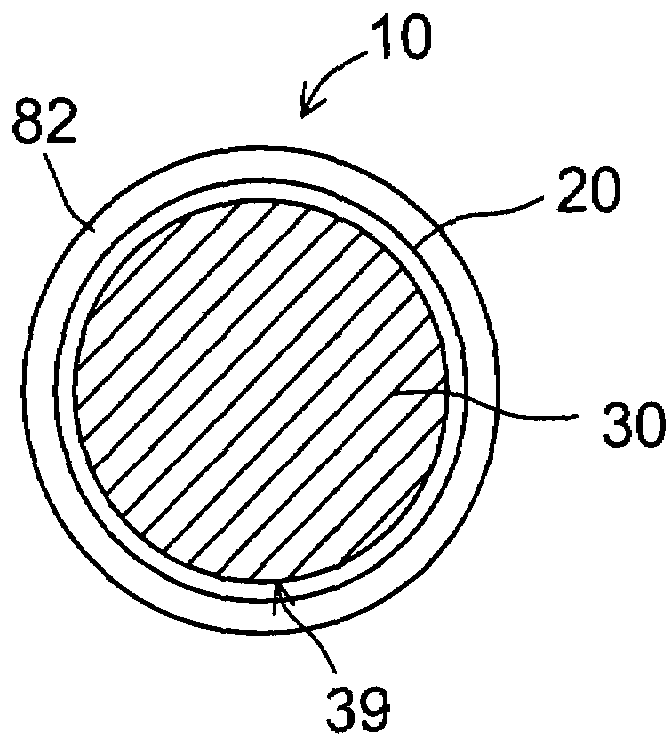
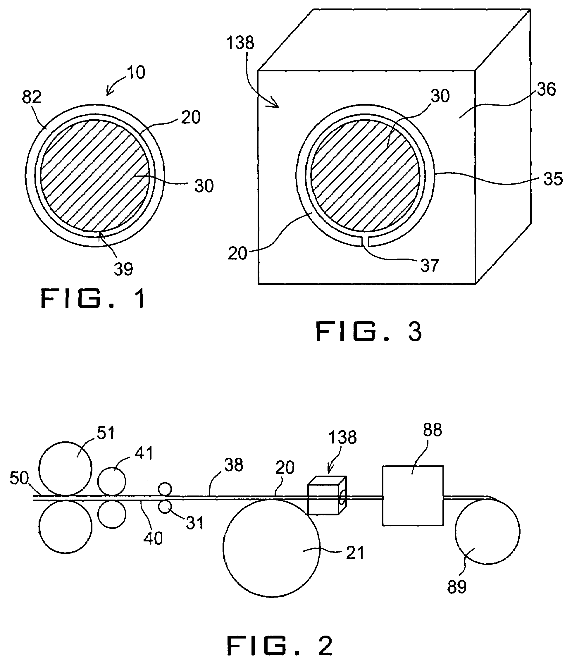
[0021]With reference to FIG. 1, ballast lead wire 10 has a core 30 of aluminum, stainless steel, or other iron core and has a cladding 20 made of copper. The installation layer 82 protects the wire 10. The copper clads around the steel and may optionally have a seam 39 the seam 39 prevents overlap and waste of copper.

[0022]In a first method, the copper is added when the lead wire is almost at the final diameter. As seen in FIG. 2, the production process diagram begins with large diameter core wire 50 that passes through large rollers 51 and intermediate rollers 41 providing a medium diameter wire. Instead of large diameter rollers 51 and intermediate diameter rollers 41, the wire can be drawn through a die also. Intermediate diameter wire 40 can further be drawn or rolled by rollers 31 into the almost final size core wire 38. The almost final size core wire 38 is only slightly larger than the final size core wire 30. A spool of copper cladding 21 unwinds copper cladding 20 that pass...


PUM

PropertyMeasurementUnit
thicknessaaaaaaaaaa
lengthaaaaaaaaaa
electronic currentaaaaaaaaaa

Abstract

Copper clad wire for ballast of fluorescent lamps is disclosed as having a core wire of a lower priced metal core than copper and a copper coating fixed on the core wire by means of a thin diffusion layer.

Description

BACKGROUND OF THE INVENTION[0001]A. Field of the Invention[0002]The present invention relates to an electric conductor. More particularly, the present invention relates to a copper clad lead wire for fluorescent lamps.[0003]B. Discussion of Related Art[0004]In modern life, fluorescent lighting is widely used in office buildings, shopping centers, warehouses, libraries and school classrooms. Fluorescent lamps have special operating characteristics, each fluorescent lamp must have a ballast to make it work properly. Not each lamp has to have a ballast to work with. Due to the availability of high-voltage and high-current semiconductors, most electronic ballast is able to drive multiple lamps and some specially designed ballasts are able to drive up to four lamps. Therefore, today's ballasts require more lead wires. Some rapid start ballast lead wire can be up to as long as 36′. The lead wires thus become a significant design consideration.[0005]In the US lighting industry, by the Nati...

Claims


Application Information

Patent Timeline
Patent Type & Authority Applications(United States)
IPC IPC(8): H01B5/00
CPCF21V23/026H01B13/0006H01B7/0009
Inventor YANG, KEVIN
Owner YANG KEVIN
Why Eureka
Try Eureka