Design of Filter Modules for Aperture-coded, Multiplexed Imaging Systems

a technology of multiplexed imaging and filter modules, applied in the field of imaging systems, can solve the problems of difficult acquisition of multiple images, large and complex systems, and difficult to capture the second spatial dimension of objects, and achieve the effect of reducing spectral crosstalk and reducing the crosstalk between different filter cells

Active Publication Date: 2012-09-06
RICOH KK
View PDF1 Cites 56 Cited by
  • Summary
  • Abstract
  • Description
  • Claims
  • Application Information

AI Technical Summary

Benefits of technology

[0013]Other aspects include different geometries for the spatial partition of the filter module, and different performance metrics depending on the desired task. In one design approach, crosstalk between different filter cells is reduced, for example reduced spectral crosstalk if the filter cells are wavelength filters.

Problems solved by technology

Acquiring these multiple images can be difficult since most commercially available sensor arrays are designed to capture one image at a time.
However, the resulting systems can be large and complicated.
However, it is difficult to also capture the second spatial dimension of the object.
However, this increases the overall cost and complexity since the amount of hardware required is significantly increased.
In addition, bulky camera systems may introduce parallax problems.
However, one disadvantage of this approach is the increased cost and complexity of manufacturing.
This may be difficult, especially if a large number of different types of micro-filters are required.
Another disadvantage is the lack of flexibility.
Once the micro-filter array is attached to the detector array, it is difficult to change the micro-filter array.

Method used


Image

  • Design of Filter Modules for Aperture-coded, Multiplexed Imaging Systems
  • Design of Filter Modules for Aperture-coded, Multiplexed Imaging Systems
  • Design of Filter Modules for Aperture-coded, Multiplexed Imaging Systems

Examples


specific examples

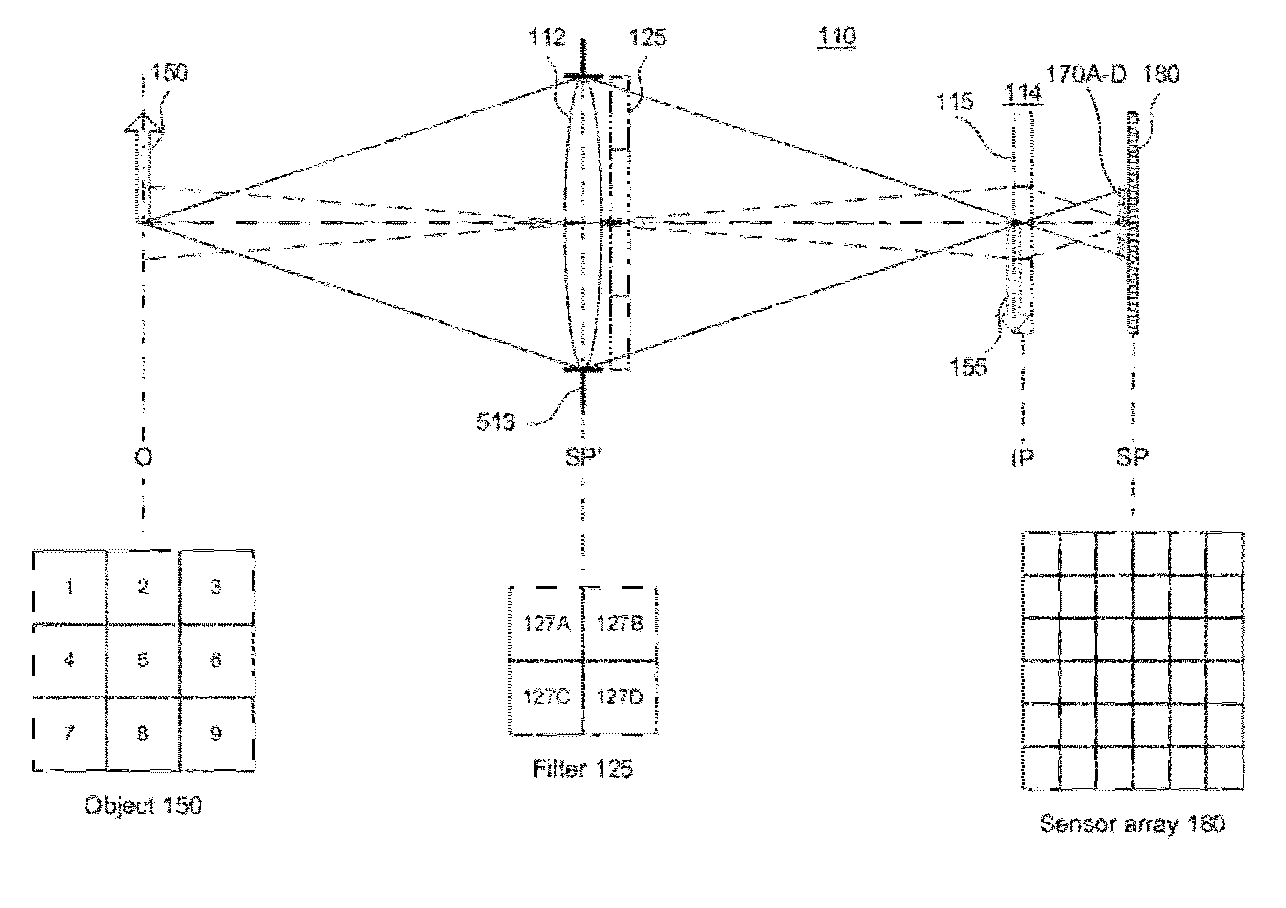
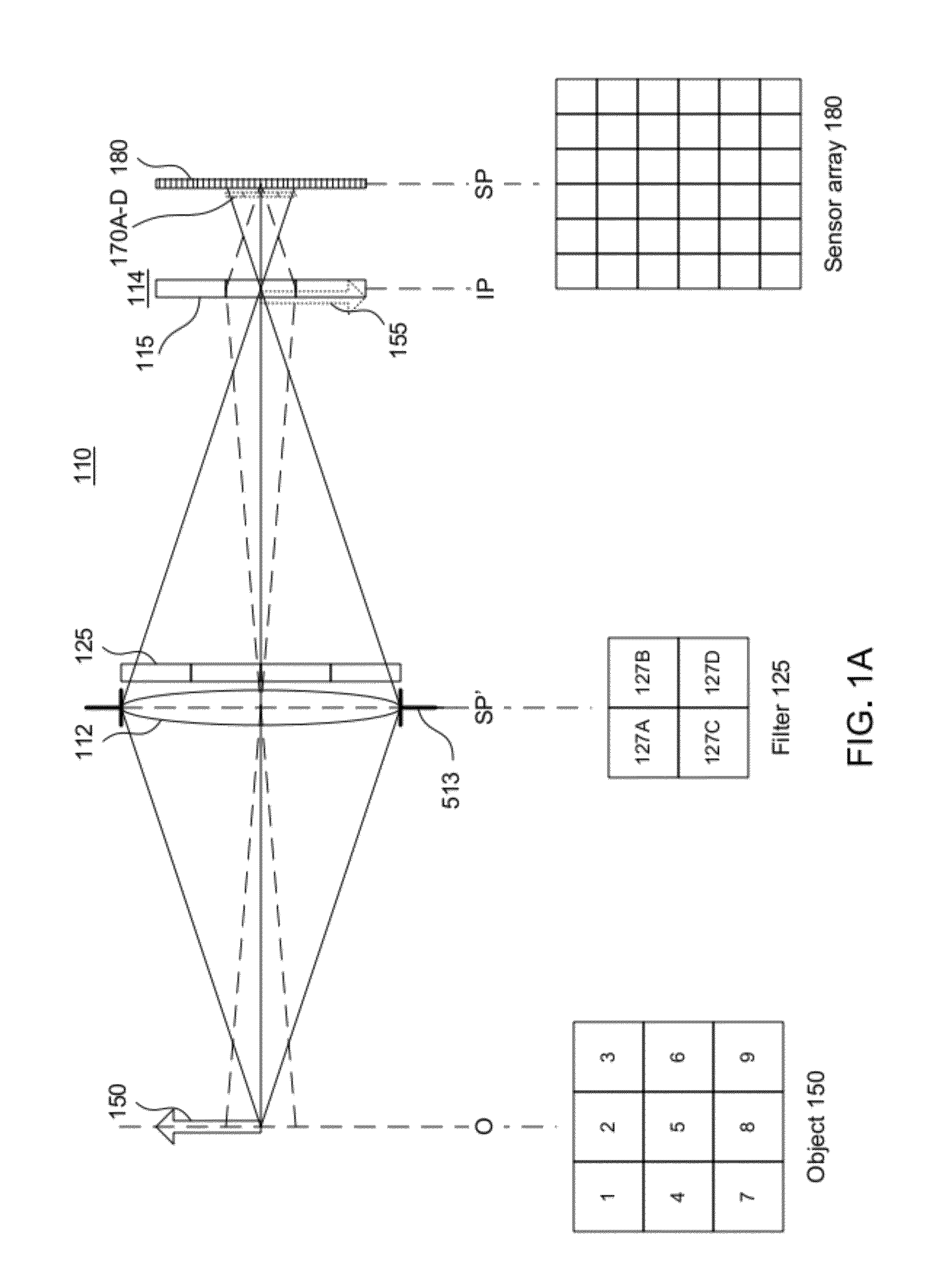
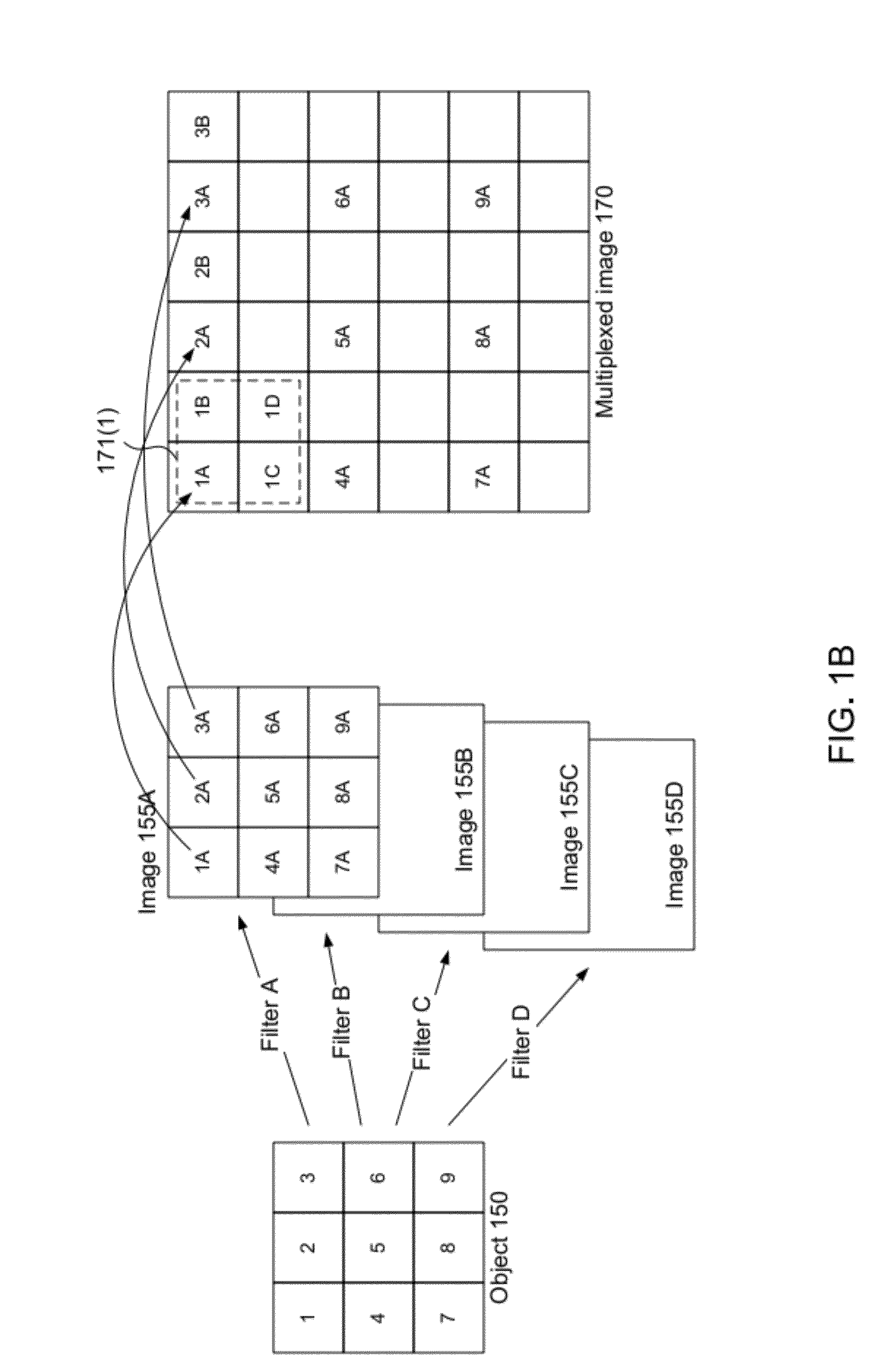
[0085]Three specific example applications are now described. The first one is the capturing of photographic information with a Bayer-pattern-type filter. In the second application, the filter module is designed for equal signal-to-noise ratios in the different captured spectral images. The third application is detecting signals in noise. All three applications use the same design parameters: main lens diameter D=40 mm, main lens focal length=50 mm, microlens diameter d=130 micron and microlens focal length=1.650 mm.

[0086]Photographic Application.

[0087]We consider a filter module that uses the RBG Bayer-pattern shown in FIG. 5C. In this case, the ring segments are compete annuli (rings) and the parameter description of the partition is as follows: N=3, M (1)=M (2)=M (3)=1; φ1,1=φ2,1=φ3,1=2π, φ0,1,1=φ0,2,1=φ0,3,1=0. That means we have only two optimization variables δ1, δ2. To simulate spectral responses for the three RGB filters we choose ρ1=450 nm, ρ2=550 nm, ρ3=650 nm.

[0088]To opti...


PUM


Abstract

A method for designing the spatial partition of a filter module used in an aperture-multiplexed imaging system. The filter module is spatially partitioned into filter cells, and the spatial partition is designed by considering data captured at the sensor in light of an application-specific performance metric.

Description

BACKGROUND OF THE INVENTION[0001]1. Field of the Invention[0002]This invention relates generally to imaging systems that can capture multiple images of the same object simultaneously, for example images of different spectral or polarization components of the object.[0003]2. Description of the Related Art[0004]There are many applications for which it may be useful to capture multiple images of the same object simultaneously. These images may be filtered in different ways, thus providing different information about the object. For example, in multispectral and hyperspectral systems, different wavelength filters may be used to acquire spectral information, and this information may then be used for spectral analysis or identification of substances or the measurement of molecules or other items labeled with fluorophores.[0005]Acquiring these multiple images can be difficult since most commercially available sensor arrays are designed to capture one image at a time. Traditionally, multipl...

Claims


Application Information

Patent Timeline
Patent Type & Authority Applications(United States)
IPC IPC(8): G06F17/50
CPCG01J1/0492G01J3/0208G01J3/0224G01J3/0229H04N9/045G01J3/2823G02B2207/129H04N5/2254G01J3/36H04N23/55H04N25/134G06F30/20G01J4/00G02B5/201G02B5/3025
Inventor BERKNER, KATHRINSHROFF, SAPNA
Owner RICOH KK
Why Eureka
Try Eureka