Soldering method, gyroscope and soldered part

Inactive Publication Date: 2012-09-13
SAGEM DEFENSE SECURITE SA
View PDF9 Cites 6 Cited by
  • Summary
  • Abstract
  • Description
  • Claims
  • Application Information

AI Technical Summary

Benefits of technology

[0029]However, these adhesives outgas strongly. This outgassing makes it difficult to create and above all to maintain a high vacuum beneath the cover. It is desirable for the electrod

Problems solved by technology

However, the submount comprises a large numbers of layers.
So, it is complex and expensive to produce in a series process.
Further, this submount presents

Method used


Image

  • Soldering method, gyroscope and soldered part
  • Soldering method, gyroscope and soldered part
  • Soldering method, gyroscope and soldered part

Examples


Example

[0041]While the invention is amenable to various modifications and alternative forms, specifics thereof have been shown by way of example in the drawings and will be described in detail. It should be understood, however, that the intention is not to limit the invention to the particular embodiments described. On the contrary, the intention is to cover all modifications, equivalents, and alternatives falling within the spirit and scope of the invention as defined by the appended claims.

DETAILED DESCRIPTION OF THE DRAWINGS

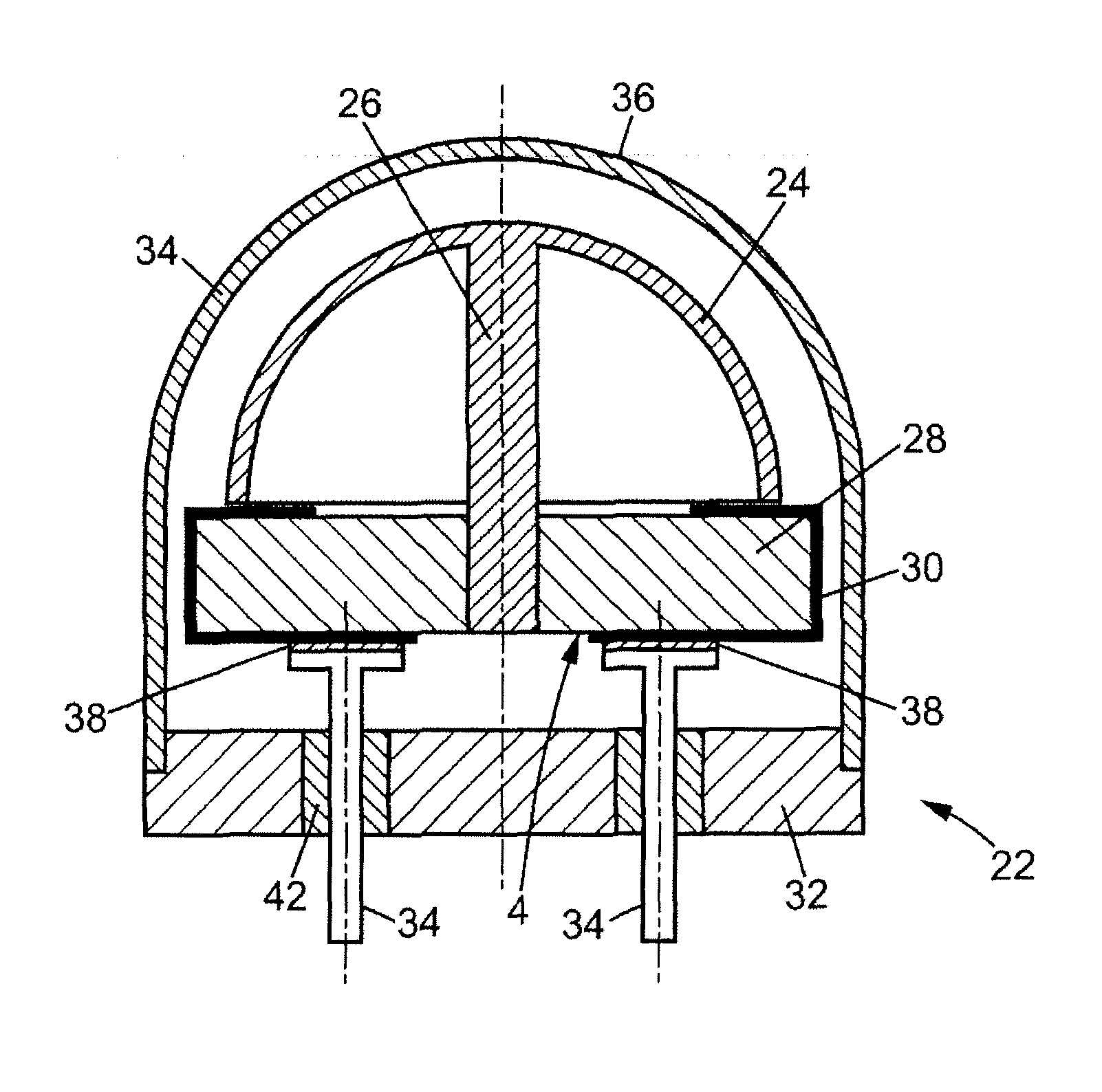
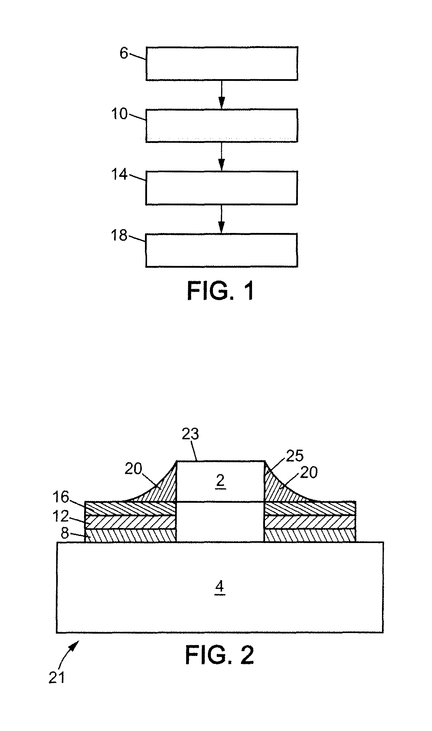
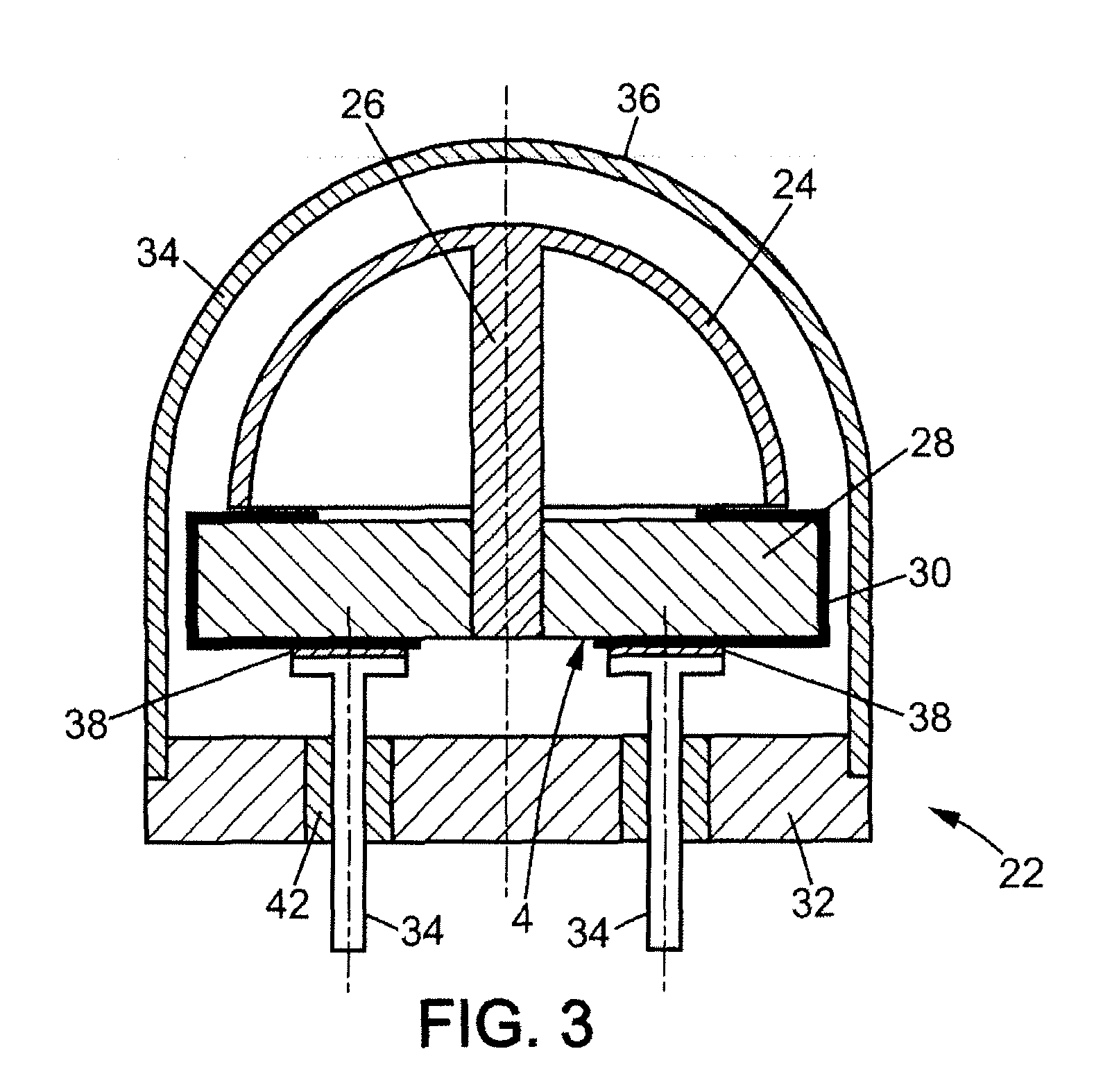
[0042]The invention relates to a method of soldering a body 2 to a substrate 4. The body 2 is at least partially conducting. It is called a conducting body hereafter. In particular, it has at least one conducting face intended to be soldered to the substrate 4. The conducting face is made of a conducting material such as, for example, a metallic material or a composite material comprising a metal.

[0043]The substrate 4 is for example formed by silica, silicon, a ceram...


PUM

PropertyMeasurementUnit
Fractionaaaaaaaaaa
Thicknessaaaaaaaaaa
Thicknessaaaaaaaaaa

Abstract

The invention relates to a method of soldering a conducting body to a substrate using an alloy chosen from either a tin-silver alloy or a tin-silver-copper alloy. The method comprises metallization of the substrate by depositing a tie layer on the substrate, depositing a diffusion barrier layer, or depositing a wetting layer comprising gold. The tie layer having any one of the chemical components chosen from chromium, titanium or titanium alloy. The diffusion barrier layer comprising a material chosen from platinum or palladium.

Description

PRIORITY CLAIM[0001]The present application is a National Phase entry of PCT Application No. PCT / EP2010 / 067221, filed Nov. 10, 2010, which claims priority from French application Ser. No. 09 / 05429, filed Nov. 12, 2009, and U.S. Patent Application No. 61 / 324,505, filed Apr. 15, 2010, the disclosures of which are hereby incorporated by reference herein in their entirety.FIELD OF THE INVENTION[0002]The present invention relates generally to gyroscopes and in particular, the invention relates to a method of soldering a conducting body to a substrate using a tin-silver alloy or a tin-silver-copper alloy, as well as to a gyroscope and to a soldered part that are manufactured by this soldering method.BACKGROUND OF THE INVENTION[0003]The invention relates to a lead-free soldering method in compliance with the directive RoHS (2002 / 95 / CE), to a gyroscope and to a soldered part that are manufactured using this soldering method.[0004]Document EP 1 542 271 discloses a method of soldering a semic...

Claims


Application Information

Patent Timeline
IPC IPC(8): B23K1/20B23K31/02G01P15/14
CPCB23K1/0016B23K35/262B23K1/19G01C19/00
Inventor VANDEBEUQUE, PAUL
Owner SAGEM DEFENSE SECURITE SA
Why Eureka
Try Eureka