Fixed focus lens

a fixed focus and lens technology, applied in the field of fixed focus lenses, can solve the problems of increasing the load on the lens driving mechanism, limiting the degree of freedom in design, and increasing power consumption

Active Publication Date: 2012-09-13
TAMRON
View PDF4 Cites 8 Cited by
  • Summary
  • Abstract
  • Description
  • Claims
  • Application Information

AI Technical Summary

Benefits of technology

0.36≦fM / f≦0.77  (4)
[0047]The fixed focus lens according to the present invention preferably satisfies the following conditional expression, where fM is the focal length of the M group and f is the overall focal length of the optical system.

Problems solved by technology

Consequently, fixed focus lenses used in single lens reflex cameras require a long back focus, limiting the degree of freedom in terms of design.
However, since the focusing group is configured by 3 or so lenses and the vibration control group is configured by 2 or so lenses, sufficient reduction of the weight of the groups is prohibited, arising in the problems of increased load on the lens driving mechanism and increased power consumption.
Nonetheless, since the vibration control group is disposed near the image plane, movement of the vibration control group in a direction orthogonal to the optical axis of the vibration control group can easily become significant.
To prevent this problem, the back focus has to be increased, which causes the overall length of the optical system to increase and thus, is undesirable.
However, during focusing, since multiple lenses, the actuator of the vibration control group, and mechanical components are collectively moved, accurate termination of the movement is difficult to maintain.
Furthermore, a large actuator for the vibration control group is necessary, arising in the problems of increased power consumption and increased lens barrel size.

Method used


Image

  • Fixed focus lens
  • Fixed focus lens
  • Fixed focus lens

Examples


Embodiment Construction

[0026]Referring to the accompanying drawings, exemplary embodiments of a fixed focus lens according to the present invention are explained in detail below.

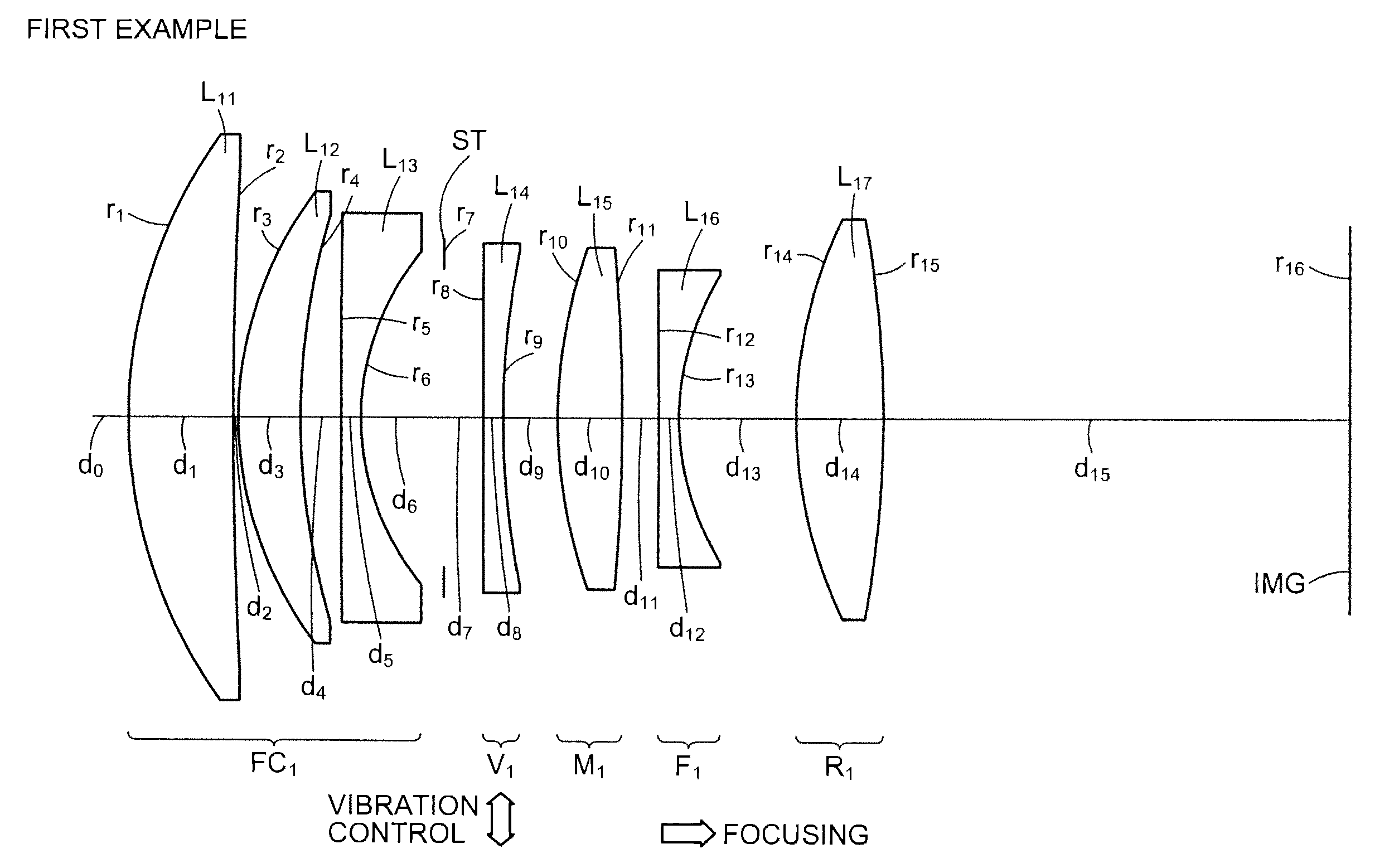
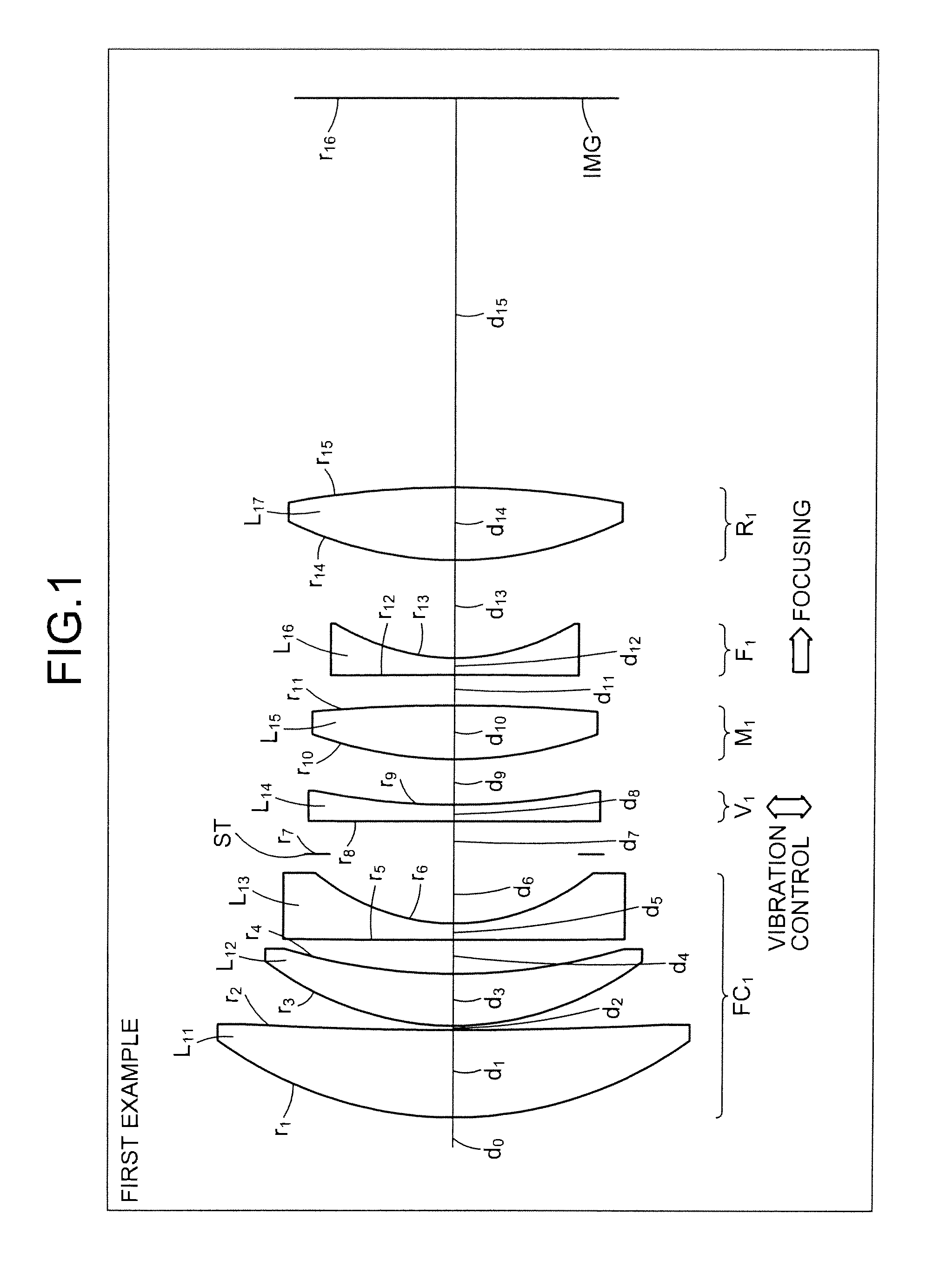
[0027]A fixed focus lens according to the present invention includes centrally in the optical system, a master (M) group that has a positive refractive power, a focusing (F) group that is disposed farther on the image plane side of the fixed focus lens than the M group and that has a negative refractive power, a vibration control (V) group that is disposed farther on the object side of the fixed focus lens than the M group and that has a negative refractive power, and a front component (FC) group that is disposed farther on the object side of the fixed focus lens than the V group and that has a positive refractive power.

[0028]In the fixed focus lens, the M group, which has a positive refractive power, is sandwiched by lens groups respectively having a negative refractive power, where the lens group on the object side of the fixed ...


PUM


Abstract

A fixed focus lens includes an M group that is disposed at a center of the optical system and has a positive refractive power; an F group that is disposed farther on the image plane side than the M group, has a negative refractive power, and is moved along the optical axis during focusing; a V group that is disposed farther on the object side than the M group, has a negative refractive index, and is moved in a direction orthogonal to the optical axis during vibration control; and an FC group that is disposed farther on the object side than the V group and has a positive refractive power. The V group is configured by a single lens element, and during focusing, at least the FC group and the M group are fixed.

Description

BACKGROUND OF THE INVENTION[0001]1. Field of the Invention[0002]The present invention relates to a fixed focus lens suitable having a vibration control function and for 35 mm cameras, video cameras, electronic still cameras, and the like.[0003]2. Description of the Related Art[0004]Single lens reflex cameras have a mechanism to make a captured image and the viewfinder image coincide. The mechanism uses a mirror disposed just in front of the film to reflect light transmitted by the imaging lens and thereby guides the light to the optical viewfinder. Consequently, fixed focus lenses used in single lens reflex cameras require a long back focus, limiting the degree of freedom in terms of design. On the other hand, digital cameras can realize an equivalent operation by merely displaying on an electronic display, the image captured by the image sensor. Consequently, “mirrorless single-lens cameras” have appeared that realize a smaller apparatus size since the optical view finder and mirro...

Claims


Application Information

Patent Timeline
Patent Type & Authority Applications(United States)
IPC IPC(8): G02B27/64G02B13/18
CPCG02B13/18G02B9/64G02B9/34G02B27/646
Inventor ADACHI, NOBUYUKI
Owner TAMRON
Why Eureka
Try Eureka