Pressure-Sensitive Steering Wheel Controls

a technology of steering wheel and control panel, which is applied in the direction of steering control, position/direction control, dashboard fitting arrangement, etc., can solve the problems of driver's thought process interruption, driver's ability to remove one or both hands from the steering wheel, and negatively affect the driver's performan

Inactive Publication Date: 2012-09-13
GUSPAN JORGE
View PDF5 Cites 50 Cited by
  • Summary
  • Abstract
  • Description
  • Claims
  • Application Information

AI Technical Summary

Benefits of technology

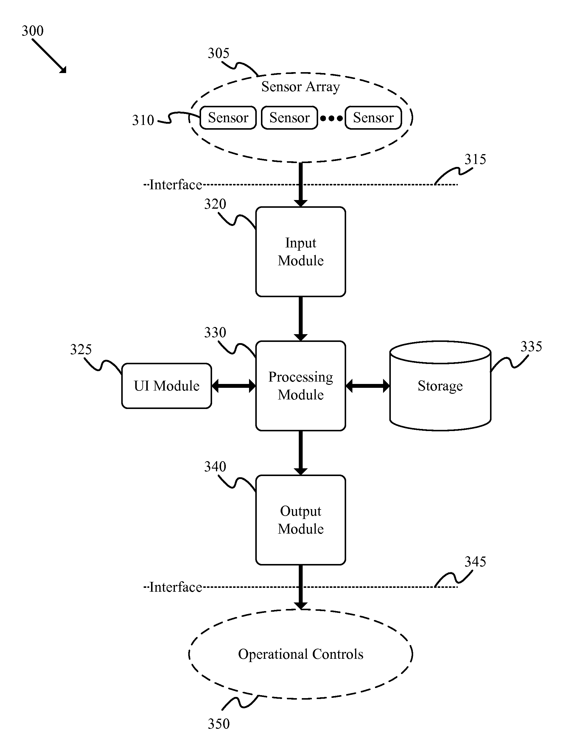
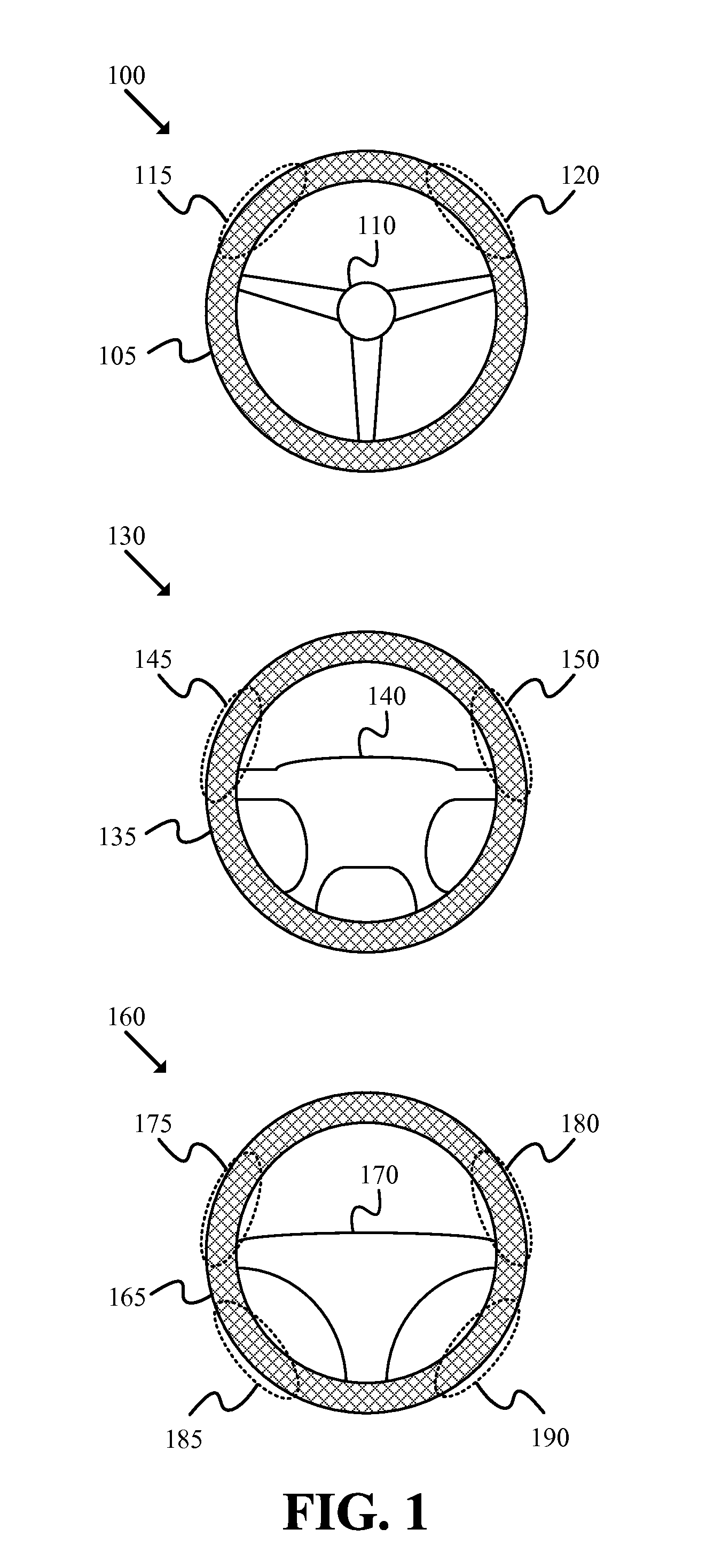
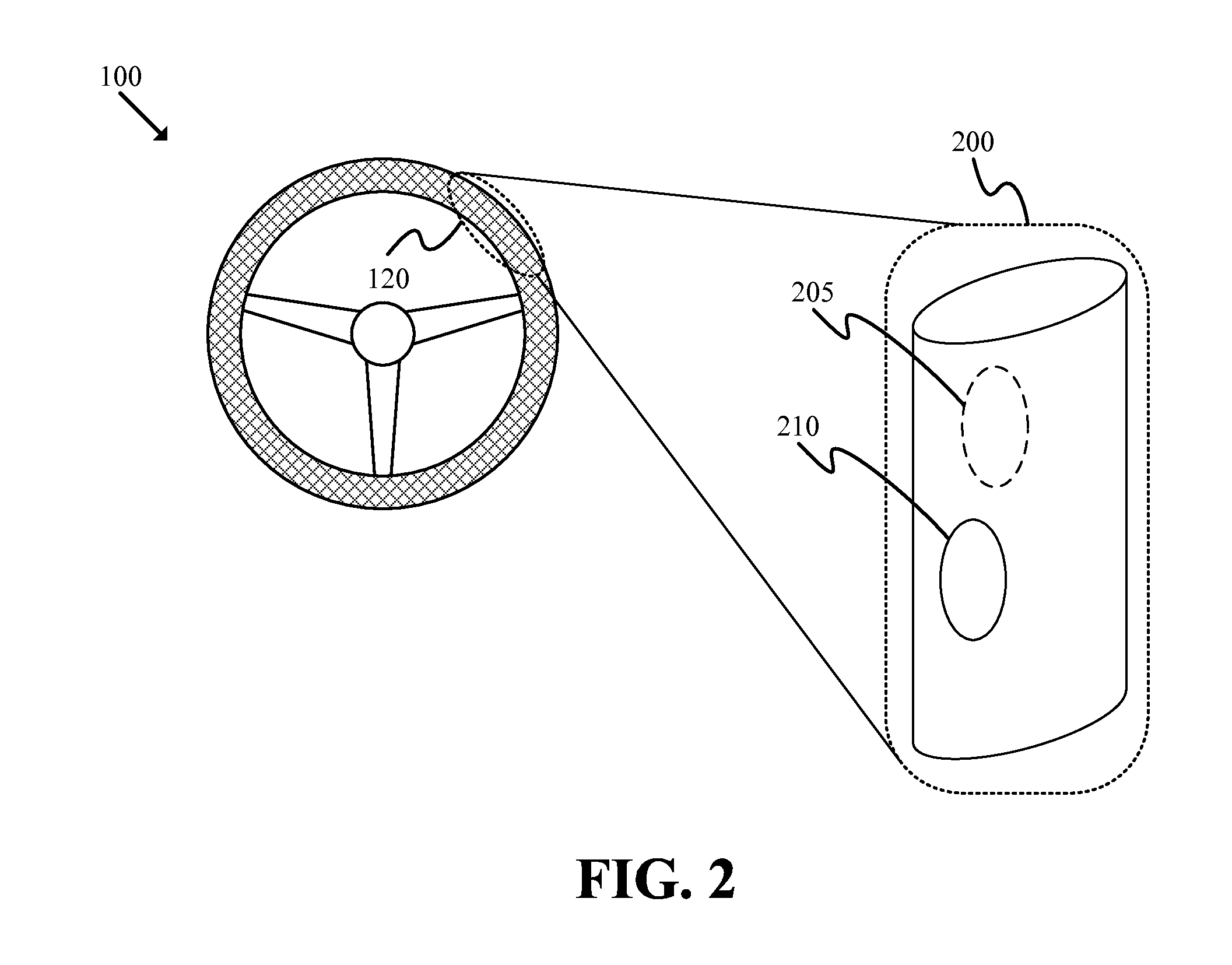
[0005]For a vehicle control that manages a particular vehicle functionality, some embodiments of the invention may provide a novel apparatus and method that allow an operator to control the particular functionality. In some embodiments, the vehicle control may include one or more arrays of sensing locations for receiving input(s) from an operator. The sensing locations in some of these embodiments may include areas placed at various positions along the steering wheel (or other control apparatus). Different embodiments may use different types and / or placements of sensing locations. For instance, the sensing locations in some embodiments may be composed of discrete sensing points that are arranged within the sensing location. In other embodiments, the sensing locations may be composed of continuous sensing regions that span the area defined by the sensing location. In some embodiments, each sensing location may include a set of one or more sensing modules, for receiving input from the operator by monitoring the output(s) of the sensing module(s).

Problems solved by technology

One difficulty in using existing solutions is that the driver has to remove one or both hands from the steering wheel (or handlebars, joystick, etc.) or keep one or both hands in contact with the wheel in order to operate the control mechanism.
Furthermore, the driver's thought processes are interrupted as the driver anticipates the need to remove a hand from the wheel before locating, grasping, and manipulating the control mechanism.
These factors can cause drivers to initiate the wrong operation (e.g., activating a turn signal rather than dimming the headlights) or otherwise negatively affect the driver's performance.

Method used


Image

  • Pressure-Sensitive Steering Wheel Controls
  • Pressure-Sensitive Steering Wheel Controls
  • Pressure-Sensitive Steering Wheel Controls

Examples


Embodiment Construction

[0021]In the following detailed description of the invention, numerous details, examples, and embodiments of the invention are set forth and described. However, it will be clear and apparent to one skilled in the art that the invention is not limited to the embodiments set forth and that the invention may be practiced without some of the specific details and examples discussed.

[0022]Although several examples above and below describe particular operations, features, etc., one of ordinary skill in the art will recognize that different embodiments may perform different operations, present different features, or otherwise differ from the examples given. For instance, although many operations are described as being performed using a steering wheel, one of ordinary skill in the art will recognize that these operations could also be performed using other types of controls (e.g., handlebars, joysticks, etc.). As another example, the sensing locations may be used for various other purposes t...


PUM


Abstract

A vehicle control apparatus, method and system are described. The vehicle control apparatus includes multiple sensing locations adapted to receive input from an operator of the vehicle, each sensing location has a set of sensing elements placed throughout the sensing location, a set of components adapted to evaluate signals produced by the sensing locations, and a set of components adapted to generate at least one output signal that controls operation of a vehicle functionality. The method receives an input signal from a pressure-sensing location, determines whether the input signal matches some criteria, and generates a control output when they match. The system includes an operator input module that receives a control signal based at least partly on pressure applied to locations along a steering control, a verification module that determines whether the received control signal matches some criteria, and an output module that activates at least one vehicle functionality.

Description

CROSS-REFERENCE TO RELATED APPLICATIONS[0001]This application claims the benefit of U.S. Provisional Application No. 61 / 449,986, filed on Mar. 7, 2011.BACKGROUND[0002]Automotive manufacturers typically provide control mechanisms that may be operated by one of a driver's hands. Such mechanisms may include physical components such as control arms, buttons, and / or twist controls, etc. These mechanisms may be used to control various vehicle functionalities such as activation of turn signals, brightening or dimming headlights, etc.[0003]One difficulty in using existing solutions is that the driver has to remove one or both hands from the steering wheel (or handlebars, joystick, etc.) or keep one or both hands in contact with the wheel in order to operate the control mechanism. In addition, different vehicles may place control mechanisms at different locations and / or use different ways of activating various vehicle functionalities (e.g., some headlights are brightened / dimmed by moving the...

Claims


Application Information

Patent Timeline
Patent Type & Authority Applications(United States)
IPC IPC(8): G06F7/00
CPCB62D1/046B60K2350/928B60K37/06B62D1/06B60K2370/782
Inventor GUSPAN, JORGE
Owner GUSPAN JORGE
Why Eureka
Try Eureka