Viscosity measuring method

Inactive Publication Date: 2012-09-20
IMAGION BIOSYST INC +1
View PDF10 Cites 6 Cited by
  • Summary
  • Abstract
  • Description
  • Claims
  • Application Information

AI Technical Summary

Benefits of technology

[0010]Practice of this embodiment of the present invention is advantageous in that the hydrodynamic diameter of the magnetic nanoparticles does not need to be precisely known; only the viscosity of the calibration fluid...

Problems solved by technology

Moreover, the calibration of the magnetic nanoparticles in the calibration fluid only needs to be pe...

Method used


Image

  • Viscosity measuring method
  • Viscosity measuring method
  • Viscosity measuring method

Examples


example 1

Viscosity Determination

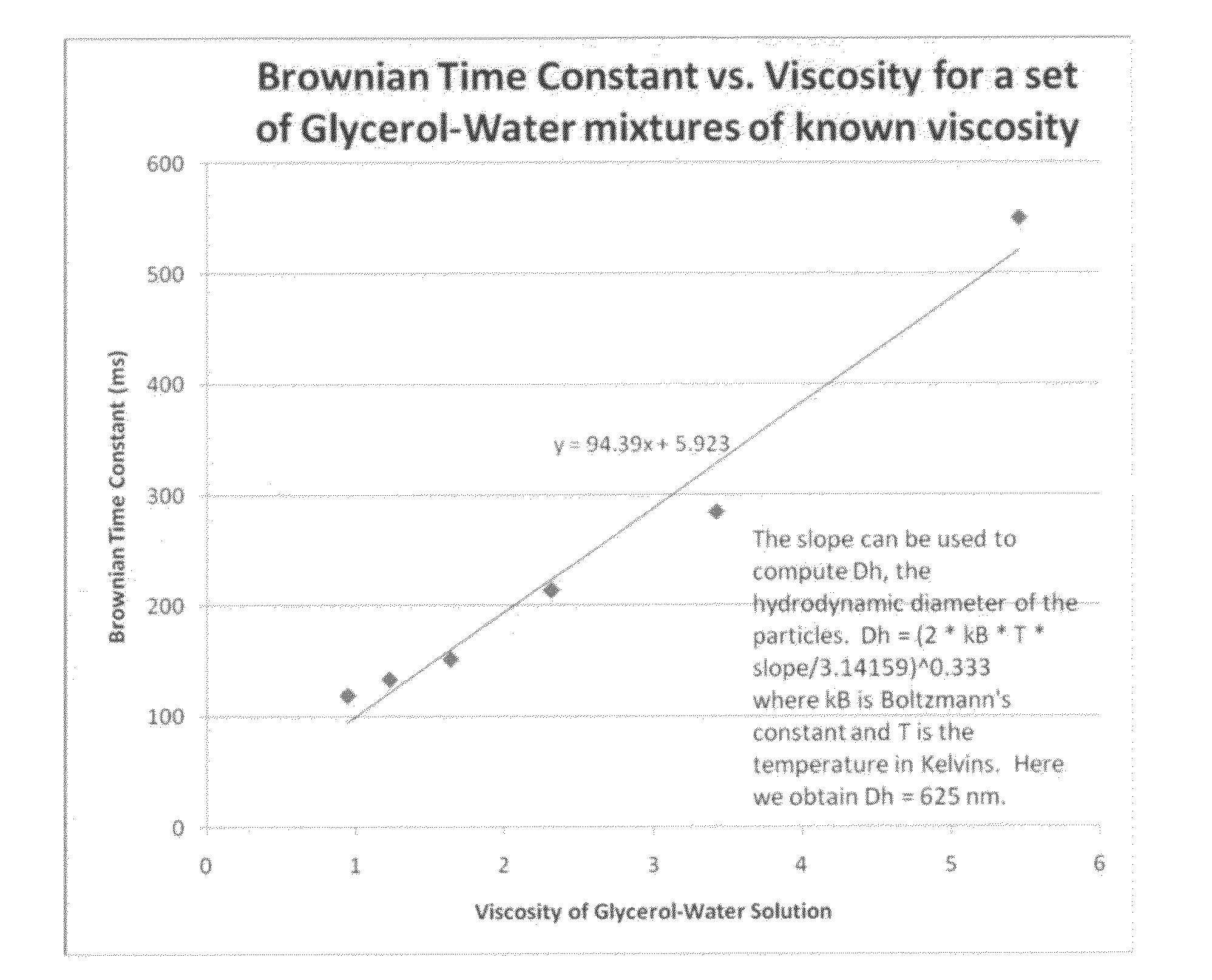
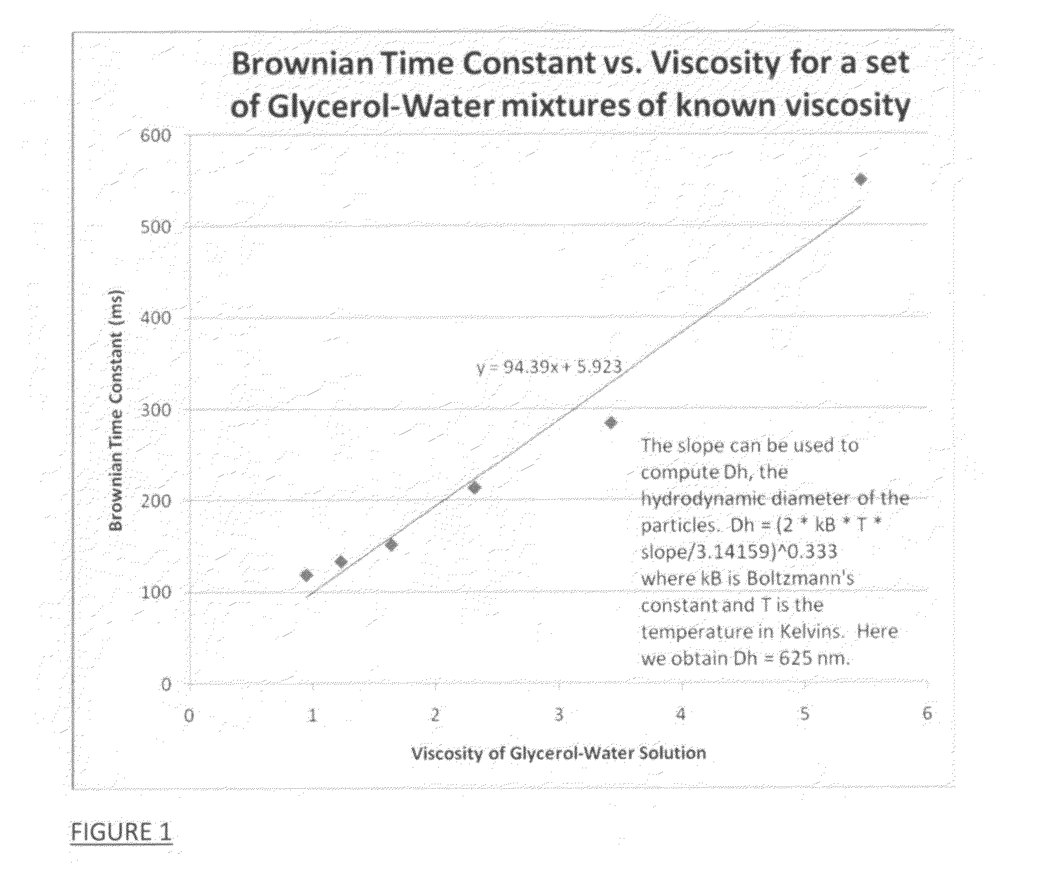
[0028]An illustrative method embodying steps 1, 2, and 3 above for a calibration fluid was conducted using a set of water / glycerol mixtures of known composition (and therefore known viscosity), as shown in FIG. 1. For the data below and in FIG. 1, the water-glycerol mixtures were prepared by a formula to give a particular set of viscosity values (plotted against the x-axis below).

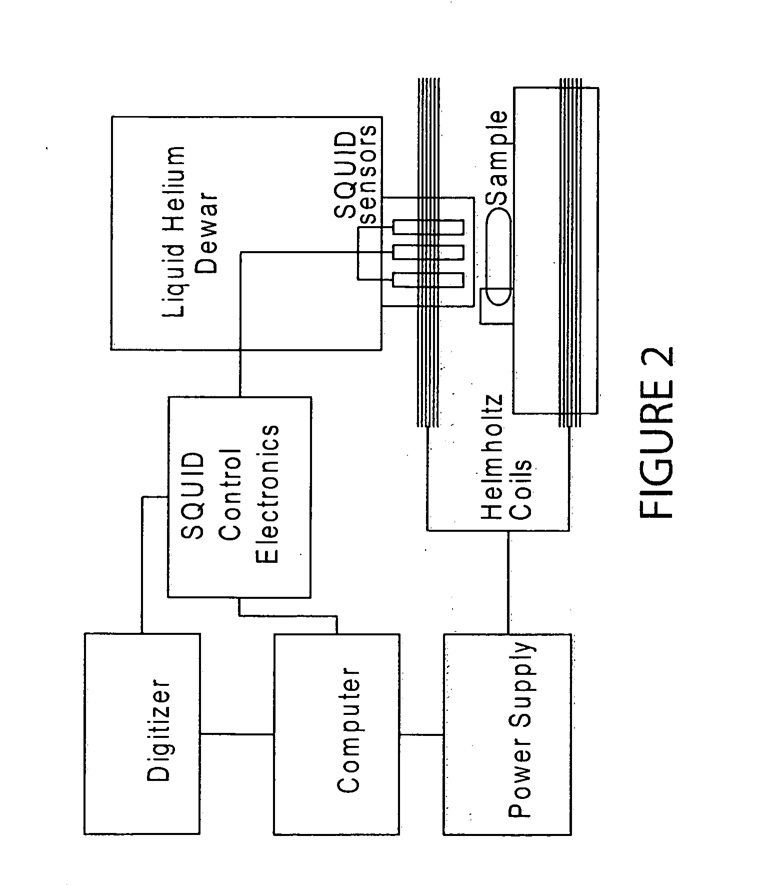
[0029]In this Example, the Brownian time constant (decay constant) was measured using the equipment schematically shown in FIG. 2 using a SQUID sensor to measure the relaxation time constant of commercially-available FluidMAG CMX magnetic composite nanoparticles of nominal 200 nm overall hydrodynamic diameter (per vendor information) in the glycerol-water mixtures, and correcting for the Neel relaxation contribution by obtaining the Neel time constant from nanoparticles dried on a cotton swab. tauN=approximately 91 ms. The FluidMAG CMX magnetic composite nanoparticles are commercially...

example 2

Preferred Relaxometry Test

[0030]In a preferred embodiment of the present invention, the magnetic nanoparticles are chosen in a manner to substantially reduce or eliminate the Neel relaxation effects on the relaxometry measurement. As a result, there will be no correction for the Neel relaxation component, as all viscosity probe nanoparticles will have a Neel relaxation time constant much longer than the measurement timescale (i.e. their magnetic relaxation will be “blocked”). In other words, it is preferred to use nearly monodisperse particles that are all “blocked” to eliminate Neel relaxation at the measurement temperature. Therefore these nanoparticles would only exhibit detectable relaxation that is caused by Brownian rotational motion, which depends on hydrodymic diameter and viscosity. In this preferred embodiment, the measured relaxation times tauS and tauW would be equal to the Brownian time constants without any need for a Neel correction factor. That is, for “blocked” part...

example 3

Hydrodynamic Particle Size Determination

[0032]The present invention envisions in another illustrative embodiment a method for determining the distribution of hydrodynamic sizes of an ensemble of magnetic nanoparticles that are introduced in a substantially homogenous “control” fluid, such as the de-ionized water calibration fluid described above, if the magnetic nanoparticles are all magnetically “blocked” at the measurement temperature as also described above.

[0033]Using steps similar those embodied in Step 3b above, the magnetic relaxometry measurement would simultaneously provide a plurality of B vs. t decay curves wherein the number of component curves would depend on the hydrodynamic particle size distribution. From a single measured B vs. t curve (the sum of the component curves), a plurality of exponential time constants (decay constants) can be determined. Obtainment of the distribution of hydrodynamic sizes involves inverting the relaxation curves using an inverse Laplace t...


PUM


Abstract

A method for measuring the average viscosity of a test fluid uses calibrated magnetic nanoparticles, with certain chosen hydrodynamic diameters and actual lateral dimensions (e.g. diameters), that are mixed into a small volume of the test fluid and a single magnetic relaxation curve measurement to provide data for viscosity determination. The distribution of hydrodynamic particle sizes of an ensemble of magnetic nanoparticles that are magnetically blocked at room temperature can be determined. Modifications of the method can be used to determine the distribution of viscosities in a complex fluid at the sub-microscopic level providing a novel type of viscosity measurement.

Description

RELATED APPLICATION[0001]This application claims benefits and priority U.S. provisional application Ser. No. 61 / 464,210 filed Mar. 1, 2011, the entire disclosure of which is incorporated herein by reference.CONTRACTUAL ORIGIN OF THE INVENTION[0002]This invention was made under grants R44 CA096154, R44 AI066765, R44 CA105742, and R44 CA123785, awarded by the National Institutes of Health. The government has certain rights in the invention.FIELD OF THE INVENTION[0003]This invention relates to a method of measuring viscosity of a fluid and, more particularly, to a method of measuring viscosity by magnetic relaxometry using magnetic nanoparticles dispersed in a test fluid.BACKGROUND OF THE INVENTION[0004]The measurement of viscosity of a fluid is important in many industries and applications where fluid properties need to be monitored and controlled.[0005]In biology and medicine, viscosity measurements are important for understanding a variety of complex biological fluids, such as engin...

Claims


Application Information

Patent Timeline
IPC IPC(8): G01N11/00B82Y15/00
CPCB82Y15/00G01N2011/0086G01N11/12
Inventor ADOLPHI, NATALIE L.FLYNN, EDWARD R.BRYANT, HOWARDBUTLER, KIMBERLY
Owner IMAGION BIOSYST INC
Why Eureka
Try Eureka