
Breakaway Hand Guard

Inactive Publication Date: 2012-09-20
ADAN ANDY
View PDF4 Cites 25 Cited by
  • Summary
  • Abstract
  • Description
  • Claims
  • Application Information

AI Technical Summary

Benefits of technology

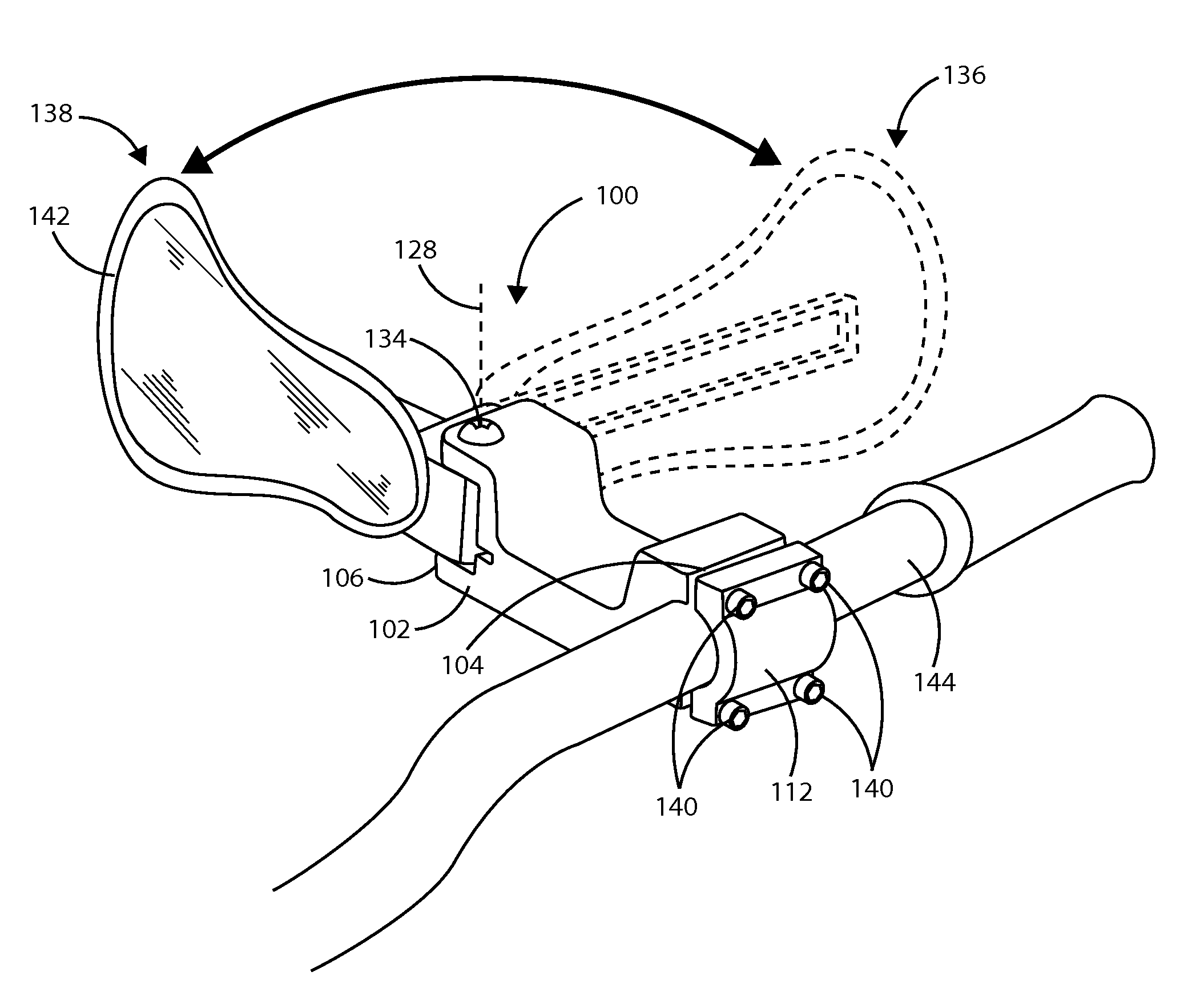
[0010]The present invention is an improved safety hand guard that provides additional safety features for increased protection to an OHV operator's hands, thereby allowing the operator to be thrown clear from the vehicle in the event of an accident.
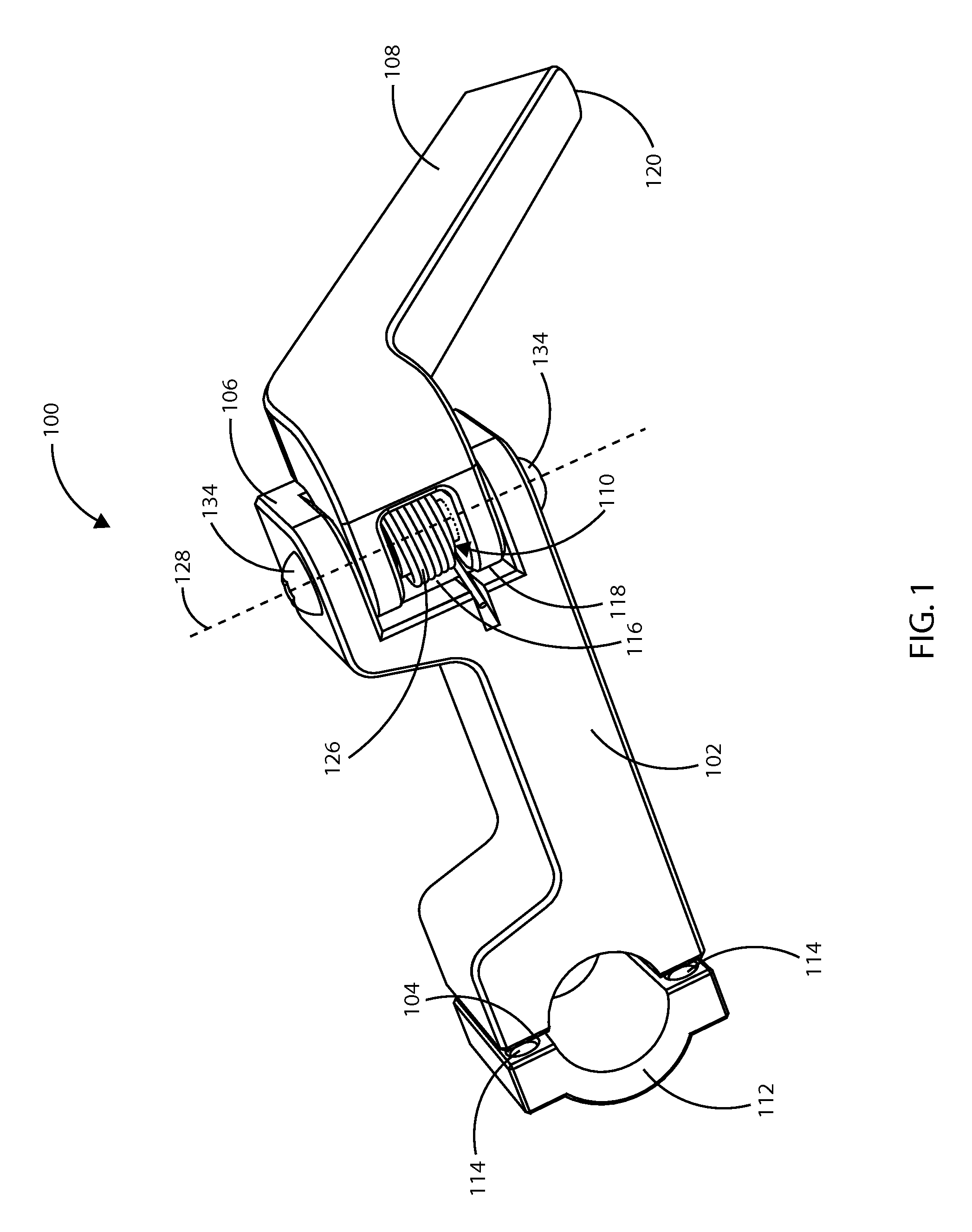
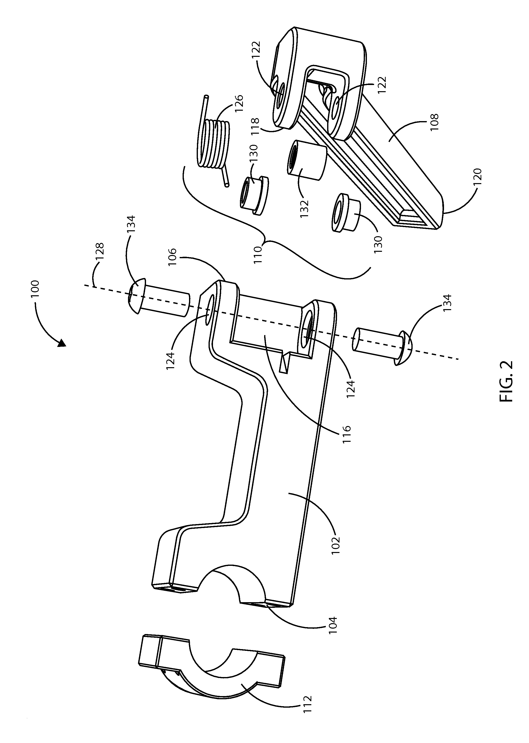
[0011]The hand guard assembly comprises a main body portion having a first end and a second end, a clamping means having a plurality of holes and an arm member having a proximal end and a distal end. The arm member is pivotally connected to the second end of the main body portion by a hinge joint assembly. The clamping means connects an off-highway vehicle handlebar to the first end of the main body portion. The clamping means preferably comprises a plurality of holes, which are threaded internally, and which fix the hand guard assembly to the handlebar of an OHV using a fastening means. The second end of the main body portion comprises a groove to receive the hinge joint assembly. Preferably, a coil spring of the hinge joint assembly urges the arm member to a closed position and provides resistance in one direction against the free rotation of the arm member relative to the main body portion about a central axis.
[0012]In the event of a front-impact accident or sudden decrease in the forward momentum of the OHV, the operator's velocity or momentum is generally not slowed or reduced to a similar degree. Hence, the operator may continue in the forward direction at a greater speed than the rest of the OHV, and as a consequence may travel over the handlebars of the OHV. In the preferred embodiment of the present invention, if the operator's arms hit the shield in a forward direction the force from the operator's momentum overcomes the opposing force imparted by the coil spring, thereby allowing the arm member to rotate around the central axis of the hinge joint assembly, ultimately providing a clear path for the operator being thrown forward relative to the vehicle. The arm member and the shield rotate to change their orientation from a first position to a second position, so that the operator's arms will not become caught or tangled between the handgrip of the handlebar and the arm member or shield of the hand guard assembly. The second position is a pre-determined position allowing safe forward passage of the operator's arm. As a result, the operator may be thrown clear off the vehicle and reduce his / her risk of being caught in the hand shield and then and / or dragged by the OHV. Once the overcoming force provided by the operator is removed, the coil spring urges the arm member to return to the first position.
[0014]A second objective of the invention is to provide an improved safety hand guard that allows the operator to be thrown clear from the OHV during a front-impact collision.

Problems solved by technology

The hands of the operator are generally on the handlebars of the vehicle and generally towards the front of the vehicle, and hence are particularly vulnerable to injuries that occur from brush, tree limbs, debris kicked up from other vehicles, and other objects that might be encountered while operating an off-highway vehicle.
When objects hit the hands of the operator directly, especially at high speeds, injury may occur that causes the operator to release the handlebars, often leading to more serious injuries.
One critical drawback of existing hand guards is that, in a frontal accident wherein the forward momentum of the vehicle is quickly reduced, the operator may be thrown in the forward direction.
When this occurs the, the operator's arms can become caught between the handlebar grip and the hand guard, preventing the operator from being cleanly thrown from the vehicle, potentially causing severe injury to the operator's arms as well as additional injuries if the operator is dragged or otherwise caught up or tangled in the space between handlebar and shield.
However, each of these hand guards suffers from the same drawback—namely that they may cause serious injury if the operator is not thrown clear over the handlebars and instead becomes trapped by his / her arm(s) in the space between the handlebars and guards.

Method used


Image

  • Breakaway Hand Guard
  • Breakaway Hand Guard
  • Breakaway Hand Guard

Examples


Embodiment Construction

[0022]In the following discussion that addresses a number of embodiments and applications of the present invention, reference is made to the accompanying drawings that form a part hereof, and in which is shown by way of illustration specific embodiments in which the invention may be practiced. It is to be understood that other embodiments may be utilized and changes may be made without departing from the scope of the present invention.

[0023]Various inventive features are described below that can each be used independently from one another or in combination with other features. However, any single inventive feature may not address any of the problems discussed above or only address one of the problems discussed above. Further, one or more of the problems discussed above may not be fully addressed by any of the features described below.

[0024]Turning first to FIG. 1, a perspective view of a hand guard assembly 100 attachable to a handlebar (not shown) of an OHV for providing safety to ...


PUM


Abstract

An improved hand guard assembly comprises a main body portion, a clamp, and an arm member. A hinge joint assembly pivotally connects the arm member to a second end of the main body portion. The clamp connects a handlebar to a first end of the main body portion. A coil spring of the hinge joint assembly restricts the free rotation of the arm member relative to the main body portion about a central axis. In a frontal accident or sudden deceleration of the vehicle, the operator's arms may hit the shield attached to the arm member in a forward direction imparting a forward force and rotating the arm member about the hinge joint assembly. The operator may then be thrown clear from the vehicle, preventing additional injuries that can occur when an operator's arms are caught between conventional hand guards and the handlebars.

Description

CROSS-REFERENCE TO RELATED APPLICATIONS[0001]This application claims priority from the U.S. provisional application with Ser. No. 61 / 453,587, which was filed on Mar. 17, 2011. The disclosure of that provisional application is incorporated herein as if set out in full. Because Mar. 17, 2012 fell on a Saturday, this application submitted Mar. 19, 2012 should be considered timely.BACKGROUND OF THE INVENTION[0002]1. Technical Field of the Invention[0003]The present invention relates in general to safety hand guards for use by an operator of an off-highway vehicle (OHV). More specifically, the present invention improves the safety of hand guards for OHV operators by providing at least one hinged hand guard having reduced resistance to force applied from one direction, decreasing the risk of injury if the operator is thrown from the vehicle.[0004]2. Background and Description of the Related Art[0005]Hand guards for protecting the hands OHV operators are currently widely in use. The OHV op...

Claims


Application Information

Patent Timeline
IPC IPC(8): B62K21/12
CPCY10T74/20822B62J23/00
Inventor ADAN, ANDY
Owner ADAN ANDY
Learn More