Malleable resilient pedestal wear plate

a resilient, wear plate technology, applied in the direction of bogies, axle boxes, railway components, etc., can solve the problems of wear plate failure, need to replace, high cost of removal and replacement, etc., and achieve the effect of improving the resistance to failur

Active Publication Date: 2012-09-20
PENNSY CORP
View PDF11 Cites 30 Cited by
  • Summary
  • Abstract
  • Description
  • Claims
  • Application Information

AI Technical Summary

Benefits of technology

The present invention introduces enhancements that make it easier to utilize and resistant to failure (such as cracks, breaks, and chip) a wear plate used on a railway truck's side frame. This improvement helps prevent damage while maintaining its effectiveness during operation.

Problems solved by technology

The technical problem addressed by this patent is the frequent replacing of worn out clip-on wear plates due to their susceptibility to cracking、chiping, and breaking. This results in high costs associated with removing and replacing these parts. An improvement in design is needed to increase the durability of wear plates and reduce maintenance expenses.

Method used


Image

  • Malleable resilient pedestal wear plate
  • Malleable resilient pedestal wear plate
  • Malleable resilient pedestal wear plate

Examples


Embodiment Construction

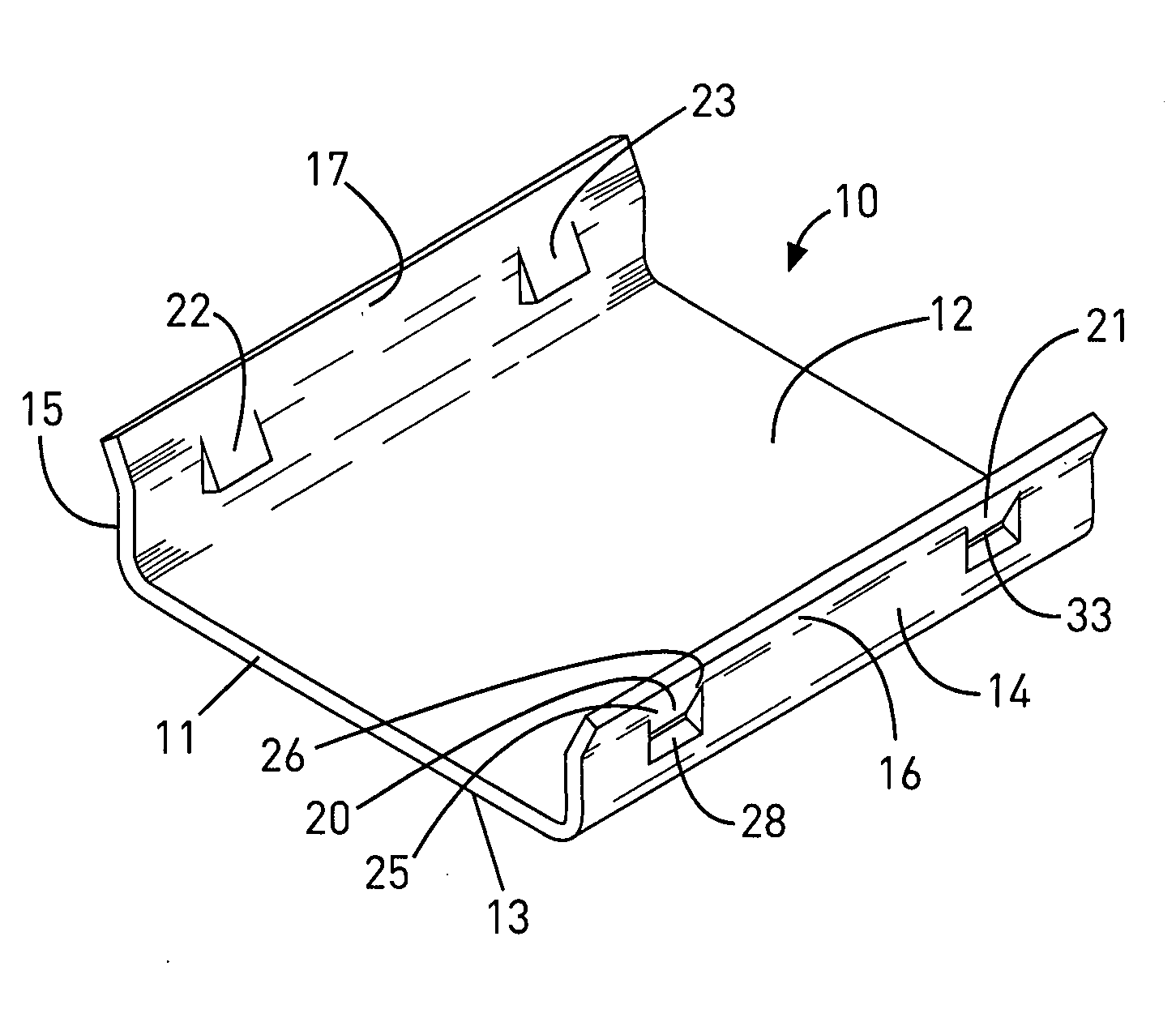
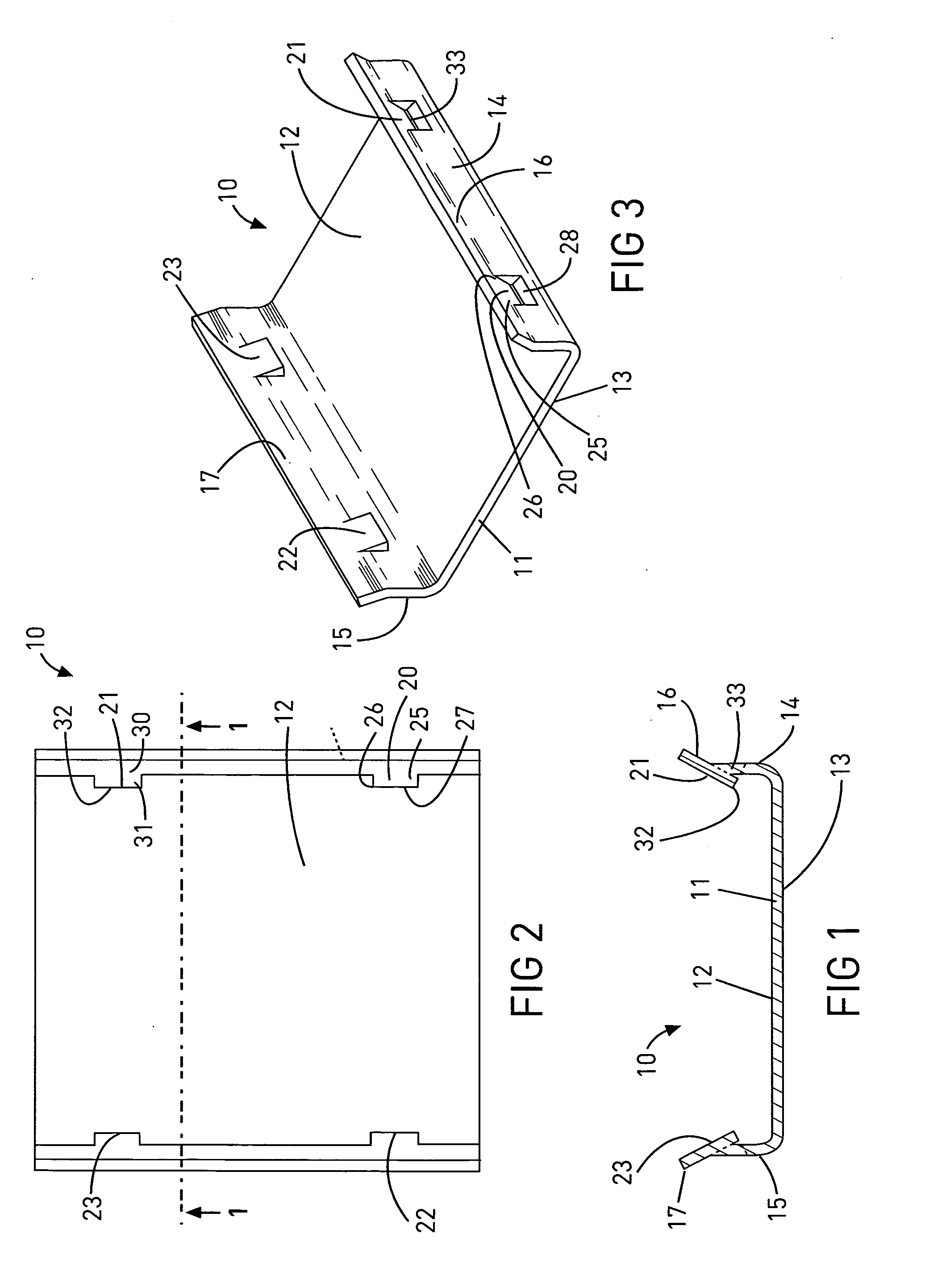
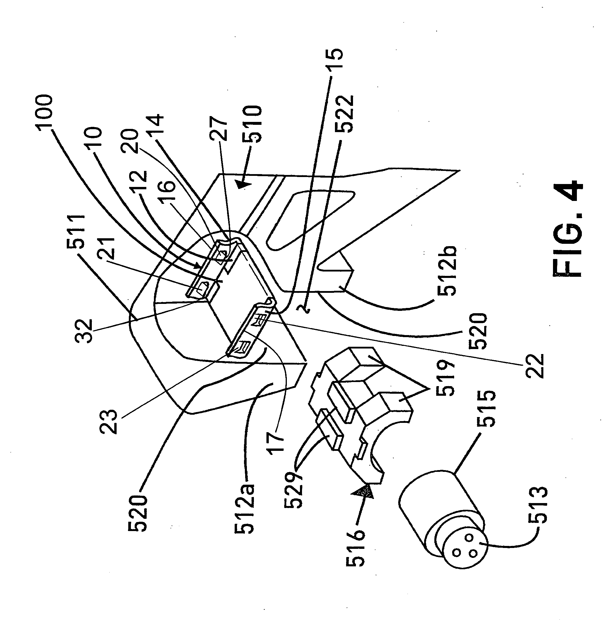
[0022]Referring to FIGS. 1-3, a wear plate 10 is illustrated having a base 11 with first or upper wear surface 12 and a second or lower wear surface 13. The wear plate 10 has side walls 14, 15 which extend upwardly from the base 11, and which preferably include outwardly turned lips 16, 17 which are disposed on each side wall 14, 15, respectively. The wear plate 10 has a locking feature for facilitating installation and securing of the wear plate 10 onto a pedestal of a railway vehicle (see FIGS. 4-6). According to a preferred embodiment, the locking feature is shown comprising projections or locking tabs 20, 21, 22, 23. The right side wall 14 is illustrated having locking tabs 20, 21 provided thereon. The locking tabs 20, 21 preferably are formed in the side wall 14 and are oriented inwardly from the side wall 14. Locking tab 20 is shown having an attached portion 25, and a free portion 26 with an engaging edge 27 (see FIGS. 1 and 2). An aperture 28 is provided in the side wall 14 ...


PUM


Abstract

A wear plate for use with a railway truck, the wear plate being configured for installation on a downwardly facing surface of a pedestal opening of a side frame of a railway truck. The wear plate includes a base and a pair of side walls extending upwardly from opposite sides of the base with inwardly disposed locking features designed to engage the pedestal when the wear plate is installed, the locking features in a preferred embodiment being configured as resilient projections that engage, clamp or drag lock onto opposite sides of the pedestal with the base of the wear plate protecting the downwardly facing pedestal surface. The wear plate may be constructed from malleable or ductile metals or plastics.

Description


Claims


Application Information

Patent Timeline
Owner PENNSY CORP
Why Eureka
Try Eureka