
Subsea valve actuator having visual manual position indicator connected to a manual override shaft

a subsea valve and actuator technology, applied in the direction of water mains, service pipe systems, gas/liquid distribution and storage, etc., can solve the problems of loss of production, environmental pollution or safety hazards, each penetration of the actuator housing involves a potential risk of sea water ingress, and the risk of bleeding from the actuator housing which is typically filled with oil or grease, so as to reduce the mechanical complexity

Active Publication Date: 2012-09-20
VETCO GRAY SCANDINAVIA
View PDF4 Cites 14 Cited by
  • Summary
  • Abstract
  • Description
  • Claims
  • Application Information

AI Technical Summary

Benefits of technology

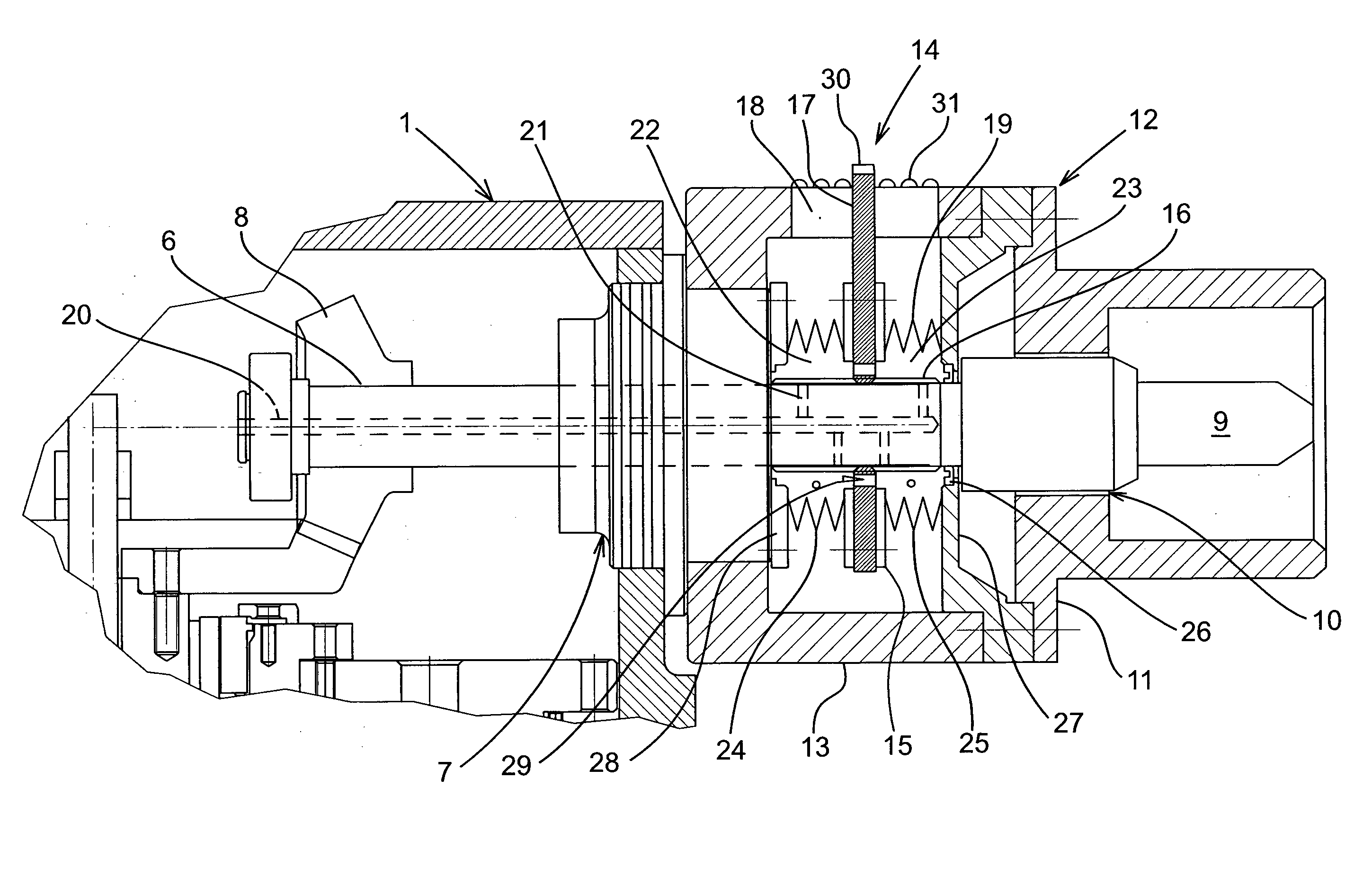
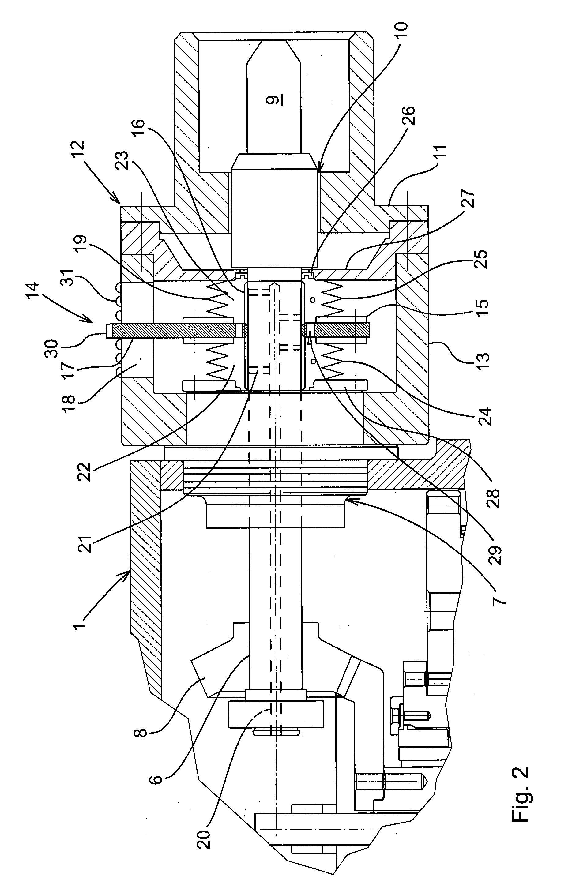
The present invention aims to reduce the mechanical complexity and the number of penetrations into the housing of a subsea valve actuator having a manual override and a visual valve position indicator which is visually readable from outside the actuator housing. The invention achieves this by introducing a visual indicator exterior to the actuator housing and pivotally mounted on the override shaft, which is forced in axial displacement on the override shaft when the override shaft is rotated. The indicator mounting enclosure is in fluid flow communication with the actuator housing, and an external pressure compensator may be located in the indicator housing. The indicator mounting enclosure is in fluid flow communication with the actuator housing via a flow passage in the override shaft. The invention also includes a carrier mounted in rotary-to-linear motion conversion engagement with the override shaft, and one or more flow passages may be formed through the carrier for fluid flow communication between the first and second chambers. The indicator mounting enclosure can be formed as an indicator housing or a part of the actuator housing. The technical effects of the invention include reduced mechanical complexity, reduced number of penetrations, and protection of the visual indicator from seawater and pressure differentials.

Problems solved by technology

An accurate operation of the valve is crucial and failure may result in loss of production, environmental pollution or safety hazards.
Besides a mechanically complex structure to ensure synchronization between the movement of the valve and the corresponding reading of the indicator, each penetration of the actuator housing involves a potential risk for ingress of sea water, or the risk of bleeding from the actuator housing which is typically filled with oil or grease.

Method used


Image

  • Subsea valve actuator having visual manual position indicator connected to a manual override shaft
  • Subsea valve actuator having visual manual position indicator connected to a manual override shaft
  • Subsea valve actuator having visual manual position indicator connected to a manual override shaft

Examples


Embodiment Construction

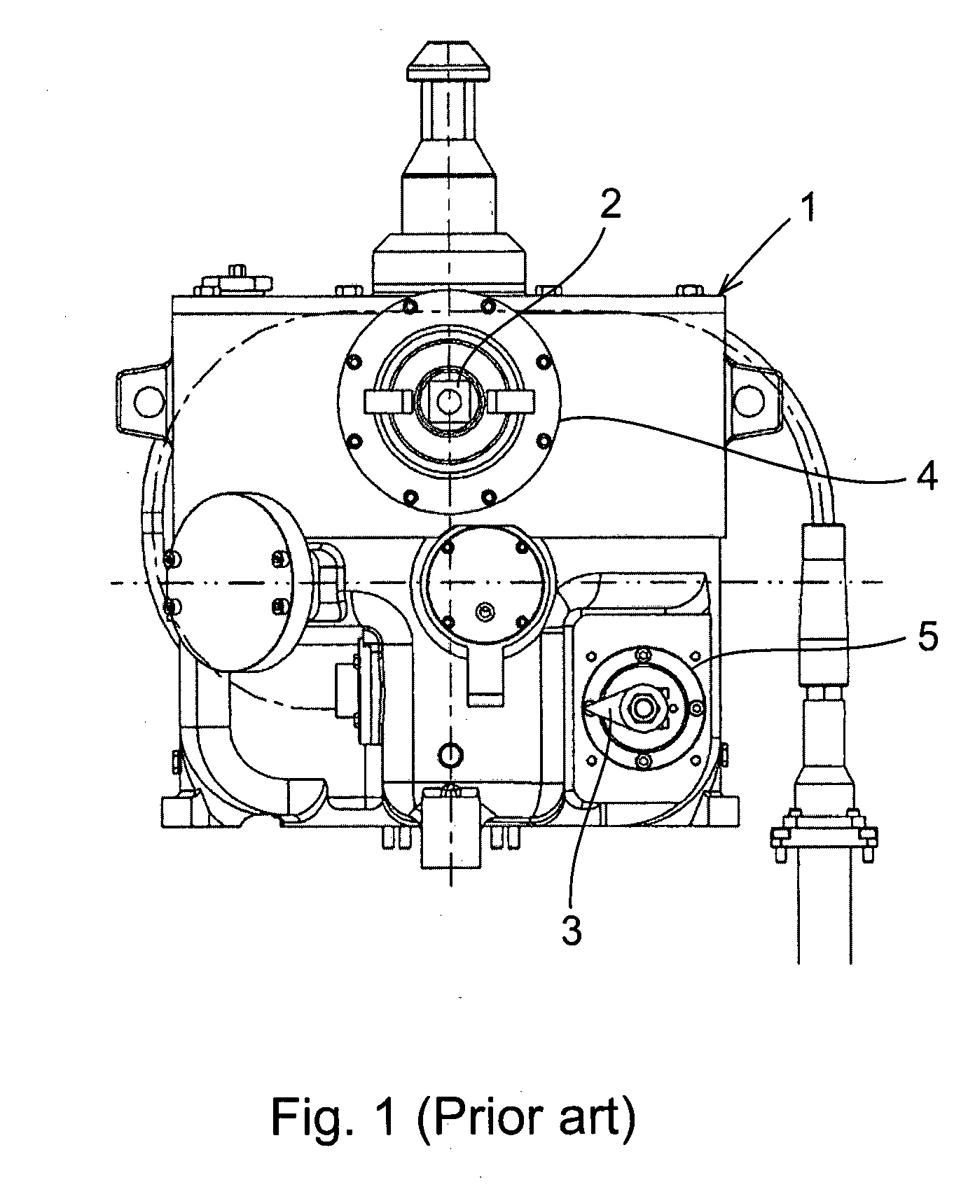
[0028]A hydraulically operated subsea valve actuator included in the prior art is shown in FIG. 1, comprising valve shifting components arranged for shifting a valve (not shown) between open and closed positions. The valve shifting components are enclosed in an actuator housing 1 which is arranged for connection to a subsea valve. An override shaft 2 and a visual valve position indicator 3 are separately introduced into the actuator housing via sealing arrangements 4 and 5, each of which provides a barrier between the ambient sea and the fluid filled and pressure compensated interior of the actuator housing 1. Inside the actuator housing, the override shaft 2 and visual indicator 3 are each and separately operatively connected to the valve shifting mechanism via pinion and reduction gear assemblies.

[0029]The combined override and visual indicator in a valve actuator according to the present invention is illustrated schematically in FIG. 2. An override shaft 6 is introduced in an act...


PUM


Abstract

A subsea valve actuator is disclosed, comprising an override shaft (6) reaching from inside a fluid filled and pressure compensated actuator housing (1) to the exterior thereof via a bearing and sealing arrangement (7), wherein a visual valve position indicator (14) is arranged exterior to the actuator housing. The visual indicator (14) is pivotally mounted to the override shaft and guided non-rotatably to be forced in axial displacement on the override shaft when the override shaft is rotated, wherein the mounting of the visual indicator (14) on the override shaft (6) is encased in a fluid filled, pressure compensated indicator mounting enclosure (19) surrounding the override shaft (6) in sealing (26) relation outside of the actuator housing (1).

Description

TECHNICAL FIELD OF THE INVENTION[0001]The present invention relates to a subsea valve actuator comprising an override shaft reaching from inside a fluid filled and pressure compensated actuator housing to the exterior thereof via a bearing and sealing arrangement, wherein a valve position indicator is arranged visible on the exterior of the actuator housing.BACKGROUND AND PRIOR ART[0002]Basically, valves for subsea production fluids operate at great depths and corresponding high pressure, low temperature and in conditions of poor visibility. An accurate operation of the valve is crucial and failure may result in loss of production, environmental pollution or safety hazards. A subsea valve is typically remotely controlled through valve actuators that are hydraulically or electrically driven for shifting the valve between open, closed and any intermediate positions. The position of the valve may be monitored remotely by means of a position sensor arranged in the actuator and connected...

Claims


Application Information

Patent Timeline
Patent Type & Authority Applications(United States)
IPC IPC(8): F16K37/00F16K31/46F16K31/00
CPCF16K37/0008F16K37/0016F16K37/0058F16K31/04Y10T137/8275Y10T137/8225E21B34/04F16K31/44F16K41/10F16K31/041
Inventor BORCHGREVINK, CHRISTIANFLIDH, JONGUIMARAES, PAULAFLIDH, CHRISTOPHER A.
Owner VETCO GRAY SCANDINAVIA
Learn More