Wavelength Selective Switch

a selective switch and wavelength technology, applied in the field of optical communication systems and components, can solve the problems of undesirable device production by arraying a plurality of complex 1n optical switching devices for wdm communication systems,

Active Publication Date: 2012-09-20
II VI DELAWARE INC
View PDF5 Cites 58 Cited by
  • Summary
  • Abstract
  • Description
  • Claims
  • Application Information

AI Technical Summary

Benefits of technology

This patent describes an optical device that can separate and combine multiple optical signals. It uses a special element called a reflective light diffracting element which splits the signal into its individual colors when it passes through. These colors are then directed by independent control over various parts of the system, allowing them to recombine at a specific point before being sent out through different channels. Overall, this technology allows for better separation and combination of color signals, improving the quality and efficiency of optical devices like lasers and sensors.

Problems solved by technology

This patent describes how wavelength division multiplexing (WDM) works in optical communication networks. It explains that WDM lets us transmit data from various sources over the same network using separate signals with distinct wavelengths. However, sometimes we have to adjust these signals individually. To achieve this, optical switching devices called wavelength selective switches (WSSs) are used. There are several types of WSDs: simple ones like 1×2 mentioned earlier, but more advanced versions like 1×N are needed when dealing with larger amounts of data. However, creating a practical 1×N WSS is challenging because it involves aligning many components accurately.

Method used


Image

  • Wavelength Selective Switch
  • Wavelength Selective Switch
  • Wavelength Selective Switch

Examples


Embodiment Construction

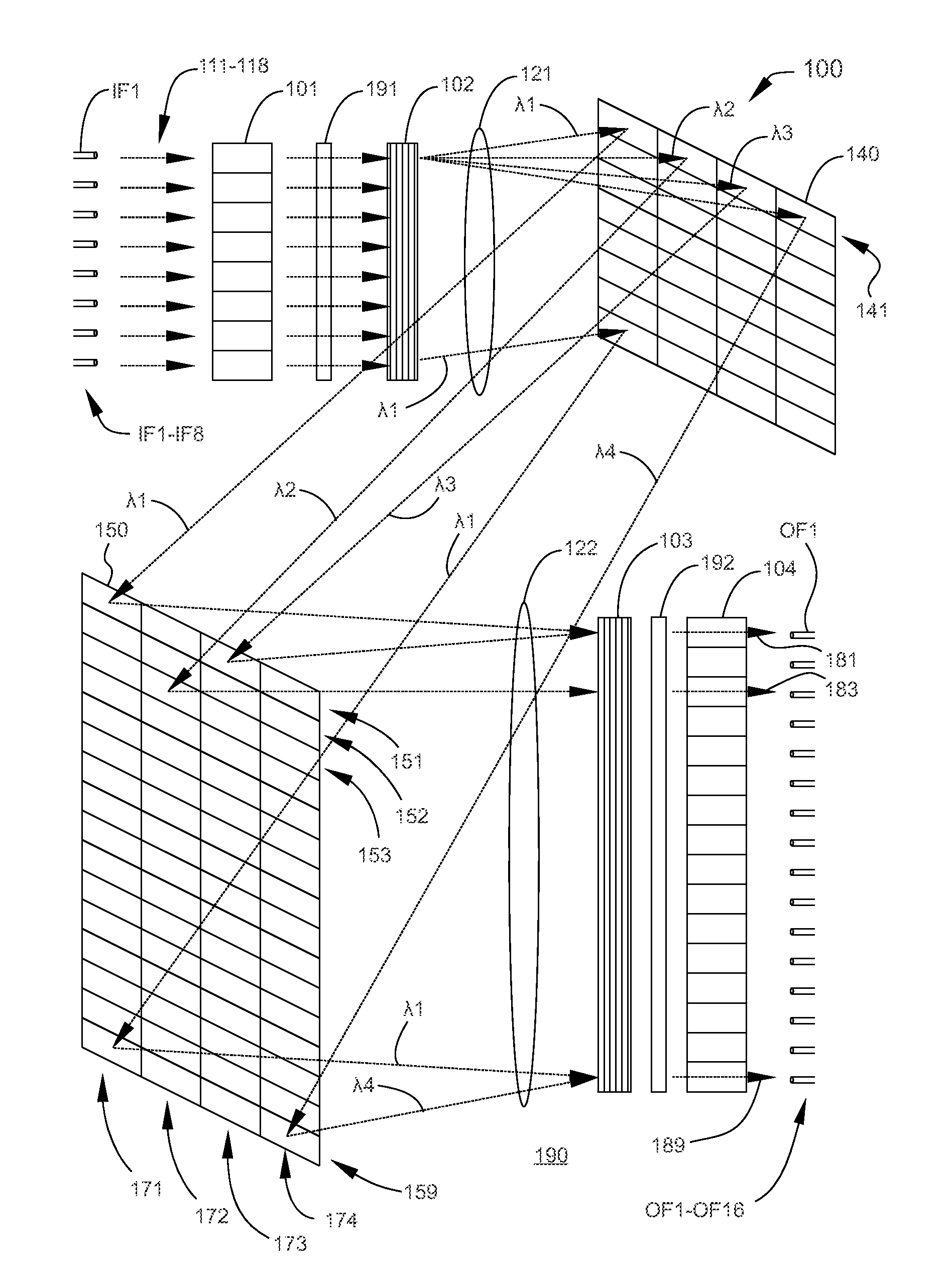
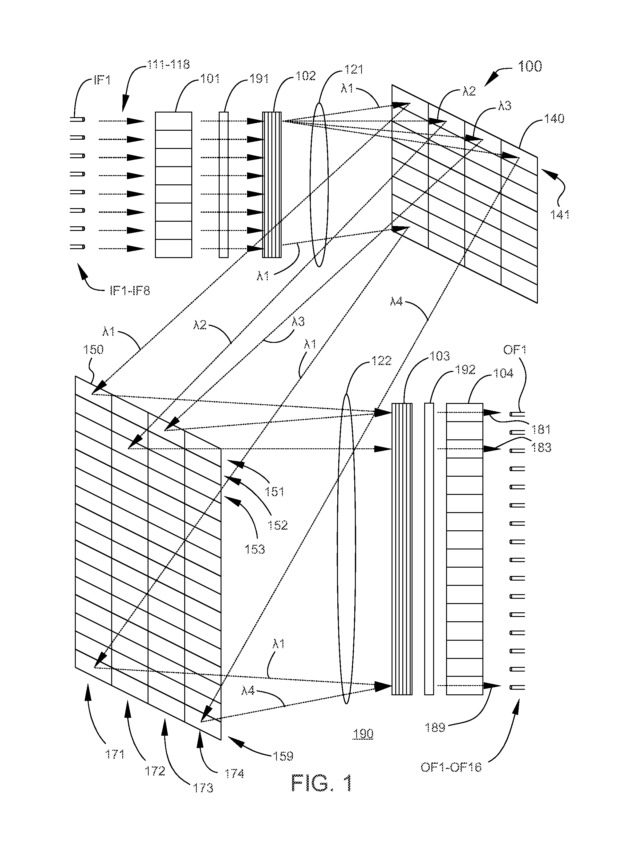
[0025]FIG. 1 schematically illustrates a perspective view of a wavelength selective switch (WSS) 100 with M×N wavelength-independent switching capability, according to an embodiment of the invention. WSS 100 is configured to provide wavelength-independent switching for each of the k wavelength components propagating through each of M input fibers to any of N output fibers. In the illustrative embodiment illustrated in FIG. 1, WSS 100 is configured for wavelength-independent switching of the k wavelength components in each of eight input fibers IF1-IF8 to any of 16 output fibers OF1-OF16. One of skill in the art, upon reading the disclosure herein, can readily devise other configurations of WSS, such as a 16×16 WSS, a 16×8 WSS, etc. Input beams 111-118 are independent WDM optical signals that contain a plurality of wavelength components, propagate from input fibers IF1-IF8, respectively, and are each optically coupled to WSS 100. For clarity, the number of wavelength components, k, f...


PUM


Abstract

An optical switching device has multiple input ports and multiple output ports and is capable of switching a wavelength component from any of the input ports to any of the output ports. The optical switching device is configured with beam steering arrays that are controlled to provide the switching from any of the input ports to any of the output ports. The beam steering arrays may be microelectromechanical (MEMS) mirror arrays or liquid-crystal on silicon (LCOS) panels. In addition, an array of beam-polarizing liquid-crystal elements provides wavelength-independent attenuation.

Description


Claims


Application Information

Patent Timeline
Owner II VI DELAWARE INC
Why Eureka
Try Eureka