
Flyback converter with leading edge blanking mechanism

a technology of flying back converter and blanking mechanism, which is applied in the direction of power conversion system, dc-dc conversion, instruments, etc., can solve the problems of exposing the flyback converter to the risk of damage, switching off wrongly, and often generating current spikes

Inactive Publication Date: 2012-09-20
AMPOWER TECH CO LTD
View PDF2 Cites 3 Cited by
  • Summary
  • Abstract
  • Description
  • Claims
  • Application Information

AI Technical Summary

Problems solved by technology

However, a current spike is often generated in the primary-side current when the switch is turned on, that is, the spike often happens in the leading edge of the primary-side current.
However, the switch is wrongly turned off as being triggered by the spike.
However, in some situations, for example, when the external power source is turned on, a great current spike exceeding the safe range may happen in the LEB time and is undesirably ignored, exposing the flyback converter to the risk of damage.

Method used


Image

  • Flyback converter with leading edge blanking mechanism
  • Flyback converter with leading edge blanking mechanism
  • Flyback converter with leading edge blanking mechanism

Examples


Embodiment Construction

[0014]Embodiments of the present disclosure will now be described in detail with reference to the drawings.

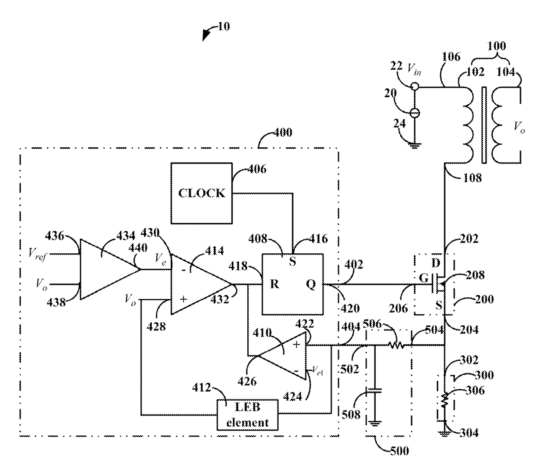
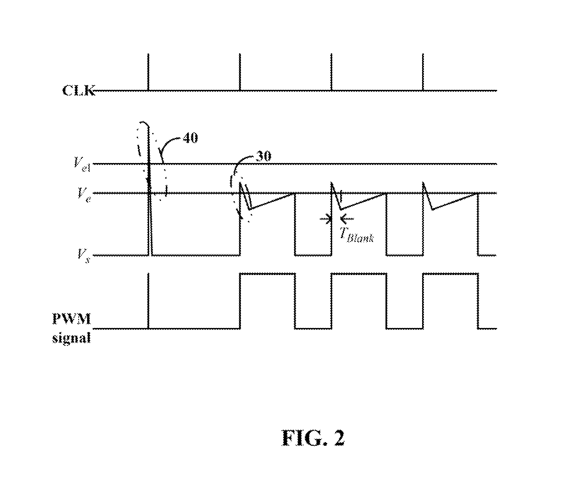
[0015]Referring FIGS. 1 and 2, a flyback converter 10, according to an embodiment, includes a transformer 100, a switch 200, a sampler 300, and a PWM controller 400. The transformer 100 includes a primary winding 102.

[0016]The primary winding 102 is electrically connected to an external power source 20 through the switch 200 and the sampler 300 when the switch 200 is turned on. The sampler 300 is configured for sampling current flowing through the primary winding 102, i.e., primary-side current, and generating a sample signal corresponding to the current. The PWM controller 400 is connected to the switch 200 and configured for generating a PWM signal configured to turn on the switch 200. The PWM controller 400 is configured for detecting whether or not the sample signal reaches a first predetermined threshold in a predetermined LEB time TBlank and turning off the switch 200 whe...


PUM


Abstract

A flyback converter having a leading edge blanking (LEB) element keeps detecting whether or not primary-side current of the flyback converter reaches a predetermined threshold, beyond which the flyback converter could be damaged, in a predetermined LEB time corresponding to a leading edge of primary-side current. The flyback converter is turned off when the primary-side current exceeds the predetermined threshold.

Description

BACKGROUND[0001]1. Technical Field[0002]The present disclosure relates to flyback converters, and particularly, to a flyback converter having a leading edge blanking (LEB) mechanism.[0003]2. Description of Related Art[0004]Flyback converters typically include a transformer, a switch, and a pulse width modulator (PWM) controller. The transformer includes a primary winding, which is electrically connected to an external power source through the switch when the switch is turned on. The PWM controller is connected to the switch and configured for generating a PWM signal which is used to control the switch on and off.[0005]When the switch is turned on as being triggered by a leading edge, e.g., a rising edge, of the PWM signal, primary-side current, that is, current flowing through the primary winding, rises and electric energy of the external power source is transferred from the primary winding to the secondary winding.[0006]To avoid the primary-side current from rising too high, which ...

Claims


Application Information

Patent Timeline
IPC IPC(8): H02M3/335
CPCH02M3/33507
Inventor GER, CHIH-CHANHUNG, TSUNG-LIANGWANG, YUN-BING
Owner AMPOWER TECH CO LTD
Features
  • Generate Ideas
  • Intellectual Property
  • Life Sciences
  • Materials
  • Tech Scout
  • Unparalleled Data Quality
  • Higher Quality Content
  • 60% Fewer Hallucinations
Learn More