Method and apparatus for controlling fans in heating, ventilating, and air-conditioning systems

a technology for heating, ventilating and air-conditioning systems, applied in the direction of instruments, heating types, static/dynamic balance measurement, etc., can solve the problems of inefficient part-load conditions, added cost to the hvac system, and sensitive to communication failures

Active Publication Date: 2012-09-20
VIGILENT CORP
View PDF6 Cites 23 Cited by
  • Summary
  • Abstract
  • Description
  • Claims
  • Application Information

AI Technical Summary

Problems solved by technology

A problem with this strategy is that it is inefficient at part-load conditions, when the flow rate is significantly lower than a design flow rate, which is the flow rate at which the system should operate when the fan is running at full speed.
One problem with resetting static pressure based on the position of the most-open terminal damper is that it requires that the control system be able to measure the position of every terminal damper.
Requiring terminal damper position measurement adds cost to the HVAC system.
Another problem with resetting static pressure based on the position of the most-open terminal damper is that it is sensitive to a communications failure.
A failure in the network connecting these devices will cause the control strategy to fail.
Yet another problem with resetting static pressure based on the position of the most-open terminal damper is that it is sensitive to a terminal unit failure.
If one of the terminal units is not working properly, then the resetting strategy will not work properly.
Yet another problem with resetting static pressure based on the position of the most-open terminal damper is that it is sensitive to a design flaw in which one or more terminal dampers is undersized.
In this case the undersized terminal damper will require high pressure to achieve its required flow, causing large throttling losses at the terminal dampers that are not undersized.
Yet another problem with resetting static pressure based on the position of the most-open terminal damper is that it is difficult to tune.
If the strategy tries to keep the most-open damper completely open then the strategy cannot determine if the duct pressure is too low.
If the controller tries to keep the most-open damper nearly completely open, then when it becomes completely open due to a disturbance in the system, the strategy cannot determine if the pressure is just slightly too low or far too low.
However, the strategy is still limited by the need for terminal damper position sensing, is still sensitive to network failure, and is still difficult to tune.

Method used


Image

  • Method and apparatus for controlling fans in heating, ventilating, and air-conditioning systems
  • Method and apparatus for controlling fans in heating, ventilating, and air-conditioning systems
  • Method and apparatus for controlling fans in heating, ventilating, and air-conditioning systems

Examples


Embodiment Construction

[0030]I. Systems Overview

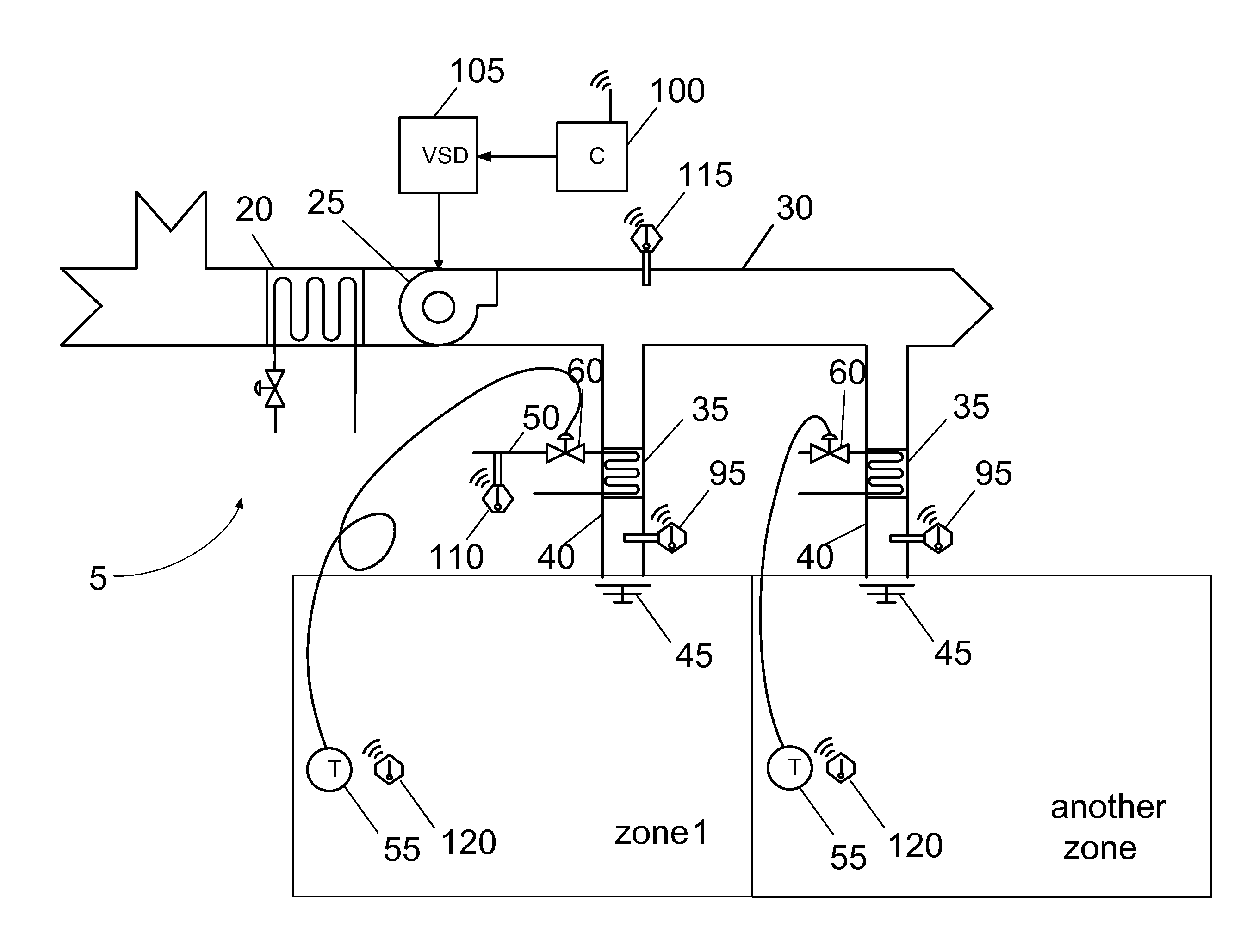
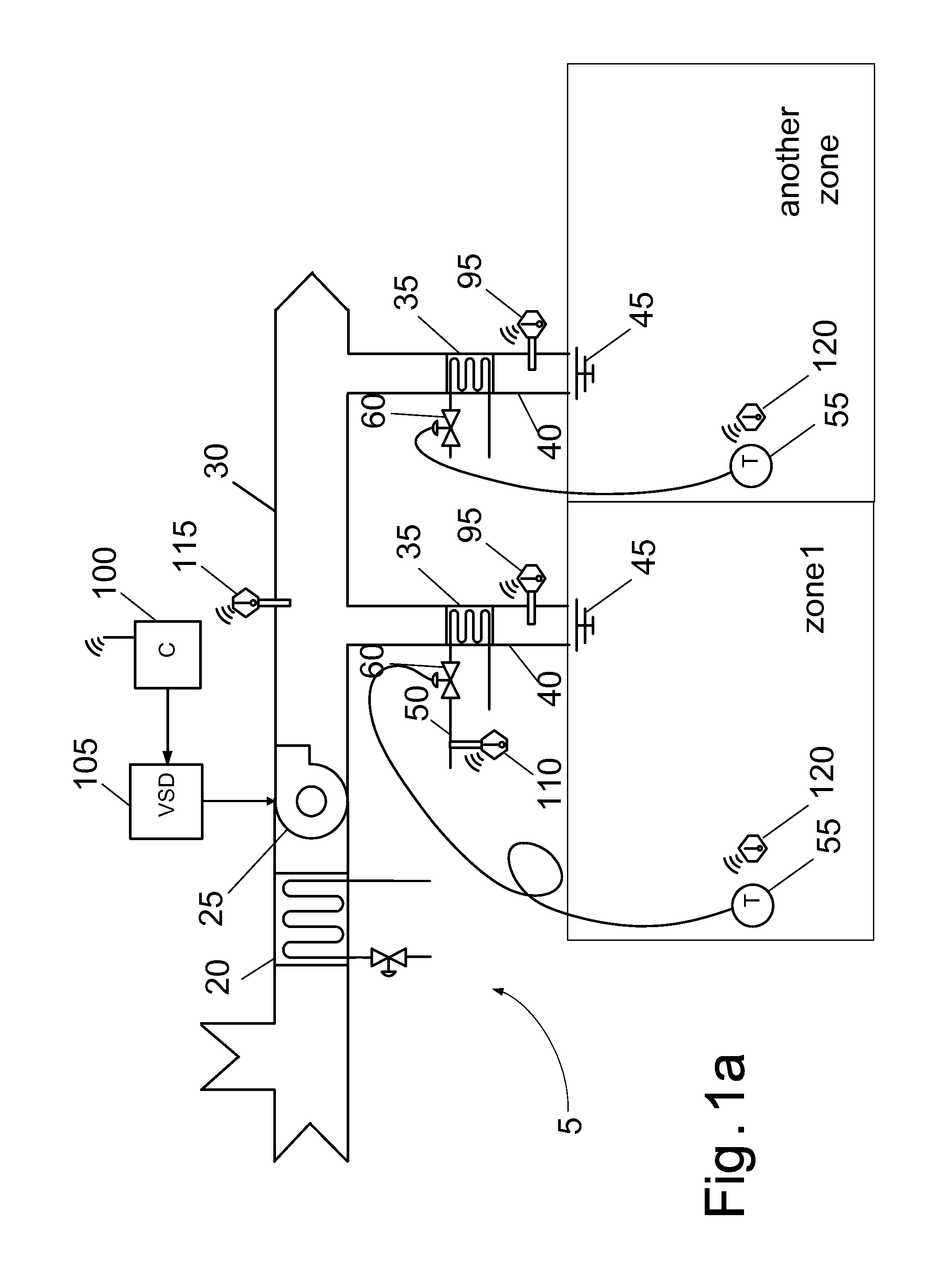
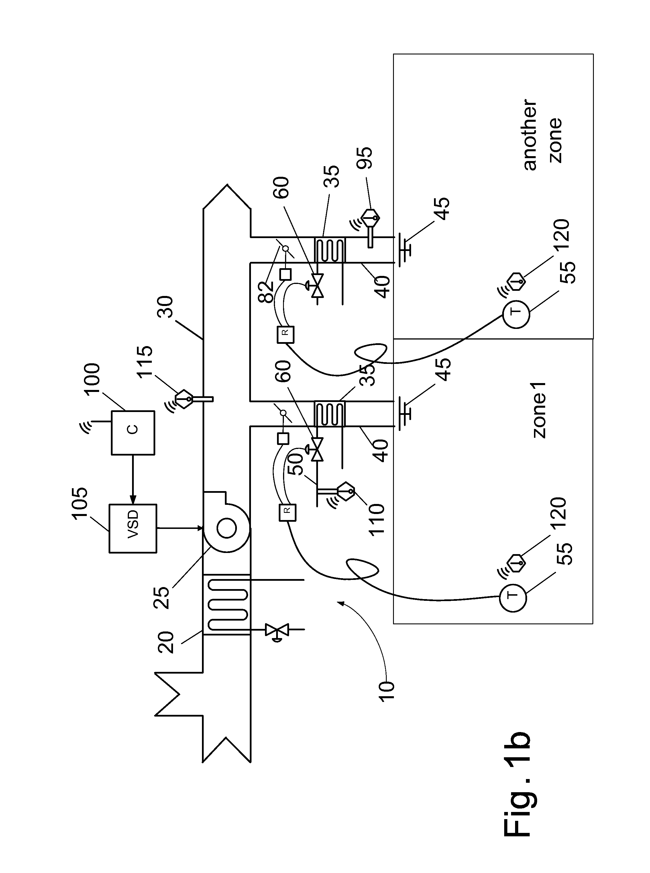
[0031]FIG. 1A shows a schematic diagram of a single-duct constant volume system 5, according to an embodiment of the invention. Single-duct systems 5 include a cooling coil 20, a supply fan 25, supply air ducts 30, re-heat coils 35, discharge air ducts 40, and discharge air diffusers 45. Cooling coil 20 is a heat exchanger that carries a cooling fluid such as chilled water or a chilled water and glycol solution. Cooling coil 20 is mounted in supply air duct 30. Supply fan 25 could be a centrifugal fan or an axial fan. Supply fan 25 is mounted in supply duct 30. A duct can be an elongate sheet metal structure with round or rectangular cross-section designed to transport air. Supply duct 30 contains branches that lead to re-heat coils 35. Re-heat coil 35 is a heat exchanger that carries heating fluid supplied by a hot water supply pipe 50. Re-heat coil 35 is mounted between a branch of supply duct 30 and discharge air duct 40. Discharge air duct 40 is a duct b...


PUM


Abstract

Systems, apparatus, and methods of controlling a variable-speed fan of an environmental maintenance module that controls temperatures of a plurality of zones of a building are provided. A first critical zone of the building is identified by analyzing the first zone temperature errors, which are used to determine a final speed setting of the variable-speed fan. Systems, apparatus, and methods of calibrating an environmental maintenance module that controls a temperature of a zone of a building are also provided. A location parameter is calculated for a plurality of zone temperatures, and a scale parameter is computed that quantifies a variation of the zone temperatures relative to a location parameter. A first temperature setpoint for the zone is determined and used in controlling the temperature of the zone.

Description

[0001]This application is a continuation application of U.S. patent application Ser. No. 12 / 426,672, entitled “METHOD AND APPARATUS FOR CONTROLLING FANS IN HEATING, VENTILATING, AND AIR-CONDITIONING SYSTEMS”, Attorney Docket No. 91725-000210US-766845, filed on Apr. 20, 2009, which claims the benefit of U.S. Provisional Application No. 61 / 046,348, entitled “METHOD AND APPARATUS FOR CONTROLLING FANS IN HEATING, VENTILATING, AND AIR-CONDITIONING SYSTEMS”, Attorney Docket No.: 027332-000200US, filed on Apr. 18, 2008, the entirety of which is incorporated by reference herein.BACKGROUND[0002]The present invention relates to controls for heating, ventilating, and air-conditioning (HVAC) systems, specifically to controlling a fan speed control for HVAC systems and calibrating HVAC systems.[0003]Modern buildings can have complex HVAC systems to control indoor temperature, pressure, ventilation rate, and other variables in a way that makes efficient use of energy. One way to conserve energy i...

Claims


Application Information

Patent Timeline
Patent Type & Authority Applications(United States)
IPC IPC(8): G05D23/19
CPCF24F11/006Y02B30/746F24F2011/0061F24F11/0079F24F11/30F24F11/62F24F11/63F24F11/77Y02B30/70
Inventor FEDERSPIEL, CLIFFORDFEDERSPIEL, KURT
Owner VIGILENT CORP
Why Eureka
Try Eureka