Image-forming device and method for forming an image

Inactive Publication Date: 2012-09-27
SEIKO EPSON CORP
View PDF4 Cites 20 Cited by
  • Summary
  • Abstract
  • Description
  • Claims
  • Application Information

AI Technical Summary

Benefits of technology

[0018]According to the aspects of the present invention as described above, positions of the edge surface of the recording material are simultaneously detected by the first through third sensors. The first shifting amount generated by movement of the recording material, the second shifting amount generated by rotation of the recording material, and a third shifting amount generated by fluctuations in the edge surface of the recording material are calculated based on the positi

Problems solved by technology

Additionally, in this device, the first edge guide is moved using the shifting detected by the first edge sensor, and the second edge guide is moved using the shifting detected by the second edge sensor, and therefore, when the i

Method used


Image

  • Image-forming device and method for forming an image
  • Image-forming device and method for forming an image
  • Image-forming device and method for forming an image

Examples


Embodiment Construction

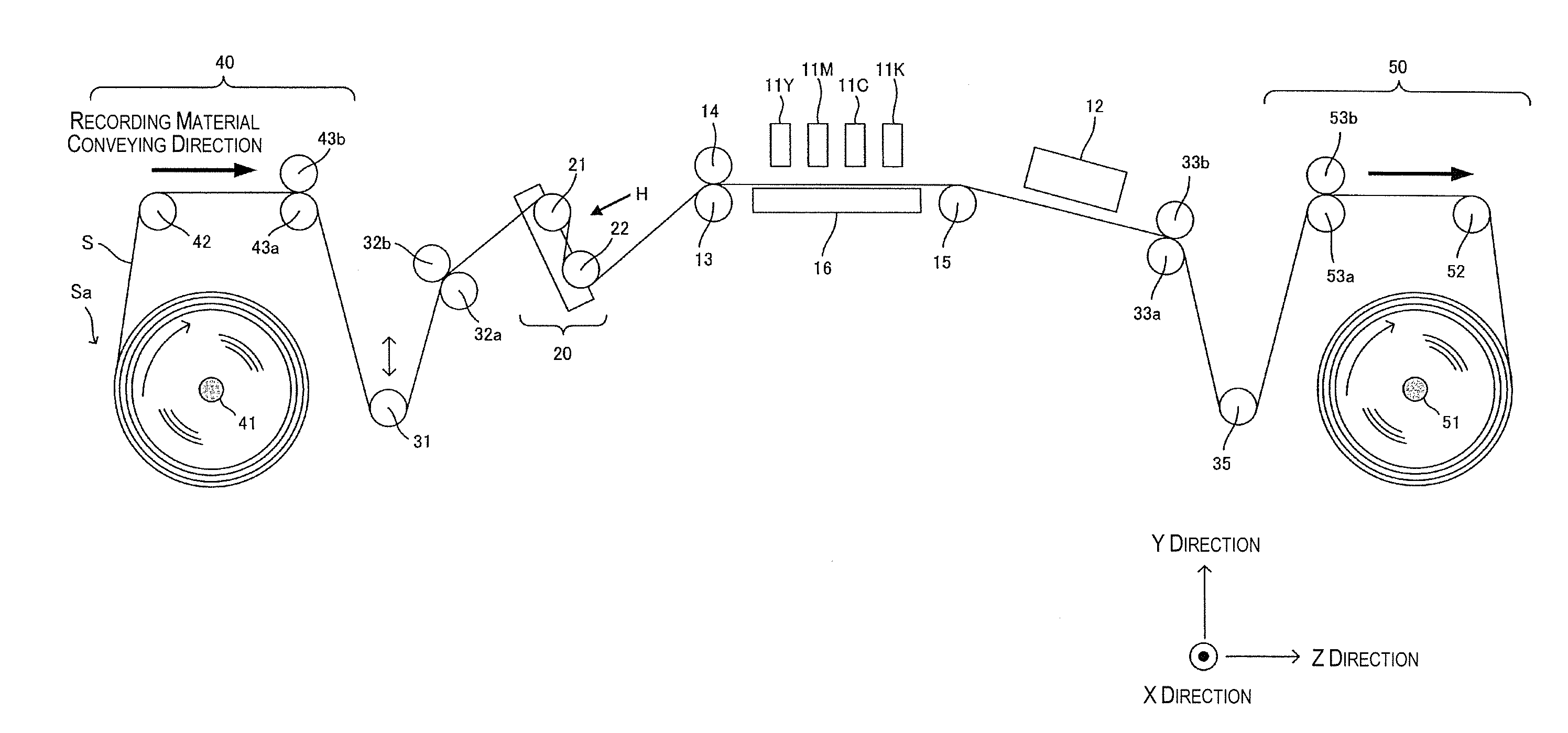
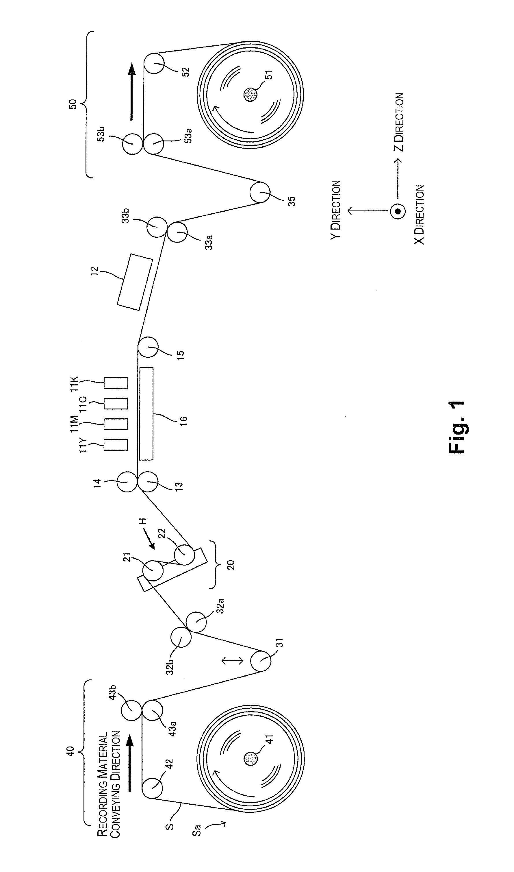
[0031]An embodiment of the present invention will be described with reference to the drawings. FIG. 1 shows the configuration of an image-forming device according to an embodiment of the present invention. The image-forming device according to the present embodiment uses photo-curing ink and is of a format involving a process in which ink is discharged from image-forming heads 11 onto a recording material S, then irradiated with light, and thereby fixed. Ultraviolet rays are employed as the light used in the present embodiment.

[0032]FIG. 1 is a lateral view of the image-forming device. As shown in FIG. 1, the direction in which the recording material S is carried is the Z direction, and the widthwise direction of the recording material S is the X direction. The primary configuration of the image-forming device includes color image-forming heads 11Y, 11M, 11C, 11K for forming (printing) pictures on the recording material S, and a conveying part comprising various rollers and the like...


PUM


Abstract

An image-forming device includes a conveying part, an image-forming part, first through third sensors, and a control part. The conveying part is configured and arranged to convey a continuous recording material. The image-forming part is configured and arranged to form an image on the recording material conveyed by the conveying part. The first through third sensors are configured and arranged to detect positions of an edge surface of the recording material conveyed by the conveying part. The control part is configured to calculate first through third shifting amounts based on the positions of the edge surface of the recording material simultaneously detected by the first through third sensors, respectively. The first shifting amount is generated by movement of the recording material, the second shifting amount is generated by rotation of the recording material, and the third shifting amount is generated by fluctuations in the edge surface of the recording material.

Description

CROSS-REFERENCE TO RELATED APPLICATIONS[0001]This application claims priority to Japanese Patent Application No. 2011-064435 filed on Mar. 23, 2011. The entire disclosure of Japanese Patent Application No. 2011-064435 is hereby incorporated herein by reference.BACKGROUND[0002]1. Technical Field[0003]The present invention relates to an image-forming device and a method for forming an image, in which image-forming heads are used to form a picture on a recording material, and particularly relates to an image-forming device and a method for forming an image in which a picture is formed on a continuous recording material.[0004]2. Related Art[0005]Image-forming devices for conveying paper, cloth, or another recording material and using image-forming parts of a plurality of colors arranged in parallel in the conveying direction to form an image on the recording material are well known. In such an image-forming device, shifting of the printing position in the conveying direction of the reco...

Claims


Application Information

Patent Timeline
IPC IPC(8): B41F1/34
CPCB41F13/025B41J11/42B41J13/26B65H9/00B41J15/046B65H23/032B41J11/0015B41J11/0095B65H23/0216
Inventor SATO, RYUICHINOMURA, YUJIRO
Owner SEIKO EPSON CORP
Why Eureka
Try Eureka