Variable-flow nozzle for cooling tower

a technology of cooling tower and water flow, which is applied in the direction of burners, compression coolers, combustion types, etc., can solve the problems of degrading the heat exchange reducing the heat exchange area between chilled hot water and air, and reducing the cooling efficiency of the cooling tower. , to achieve the effect of reducing the cooling efficiency, widened the water flow range of the cooling tower

Inactive Publication Date: 2012-09-27
WUXI YONGXIN ENERGY TECH
View PDF4 Cites 1 Cited by
  • Summary
  • Abstract
  • Description
  • Claims
  • Application Information

AI Technical Summary

Benefits of technology

[0009]Comparing the water spraying nozzles in the prior art, since an upward extension section is added to the upper part of the water distribution channel in the present invention and multi-layer water inflow openings are arranged on the periphery of the extension section or inverted conical water inflow slots are arranged on the periphery of the extension section, the water spraying nozzle can regulate the water inflow in a self-adapting manner according to the water inflow, and thereby even water distribution to the nozzles away from the water inlet can still be ensured when the water flow is low, even water spraying on the entire cross section of the water distribution channel can be achieved, and the cooling efficiency of the cooling tower will not be degraded; in addition, the variable range of the water flow in the cooling tower can be widened, and variable flow-rate cooling towers can be implemented. Therefore, the nozzle provided in the present invention is particularly suitable for the variable flow-rate cooling water systems for central air conditioning systems.
[0010]Specifically, an upward extension section is added to the existing water spraying nozzle or nozzle adapter in the wa

Problems solved by technology

The bigger the cooling tower structure is, the more severe the phenomenon will be.
Consequently, the heat exchange area between chilled hot water and air will be reduced, and the heat exchange efficiency of the cooling tower will be degraded and lower than the design efficiency.
In practice, a solution is to utilize sprinklers or sprinkler interfaces with different apertures according to the water inflow, so as to ensure even water distribution to the nozzles, however, that solution is troublesome, because the water inflow into the cooling tower varies frequently

Method used


Image

  • Variable-flow nozzle for cooling tower
  • Variable-flow nozzle for cooling tower
  • Variable-flow nozzle for cooling tower

Examples


embodiment 1

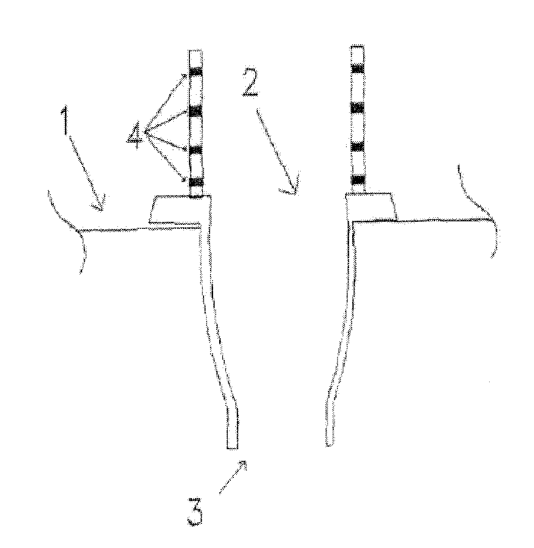
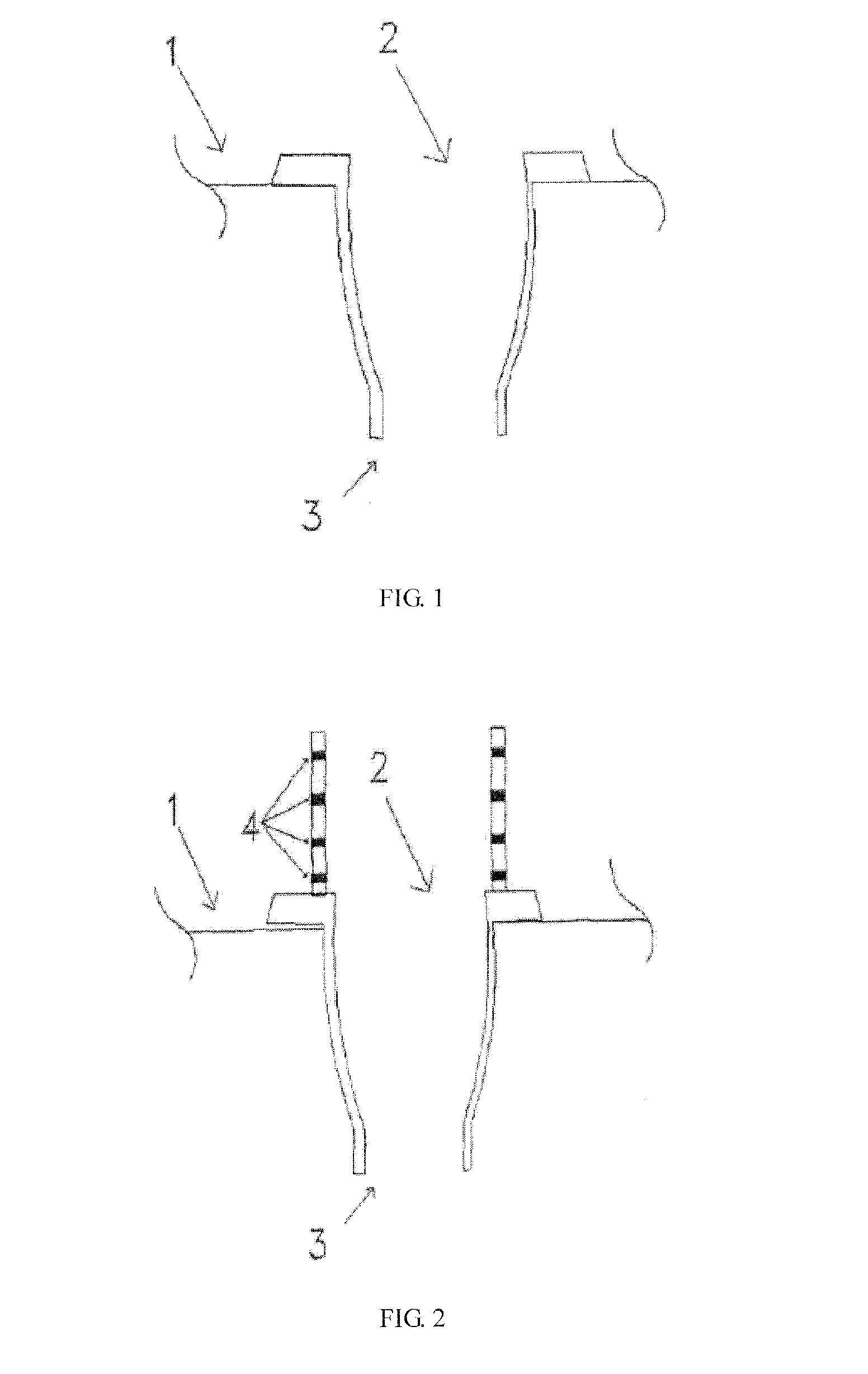
[0015]As shown in FIG. 2, the water spraying nozzle 3 for cooling tower in the present invention has an upward extension pipe section 6 (extension pipe section of water inflow pipe 2) with sealed plug-in connection in a water distribution channel 1, and the extension pipe section has multi-layer water inflow holes or vertical slots arranged on the periphery thereof at different elevations.

embodiment 2

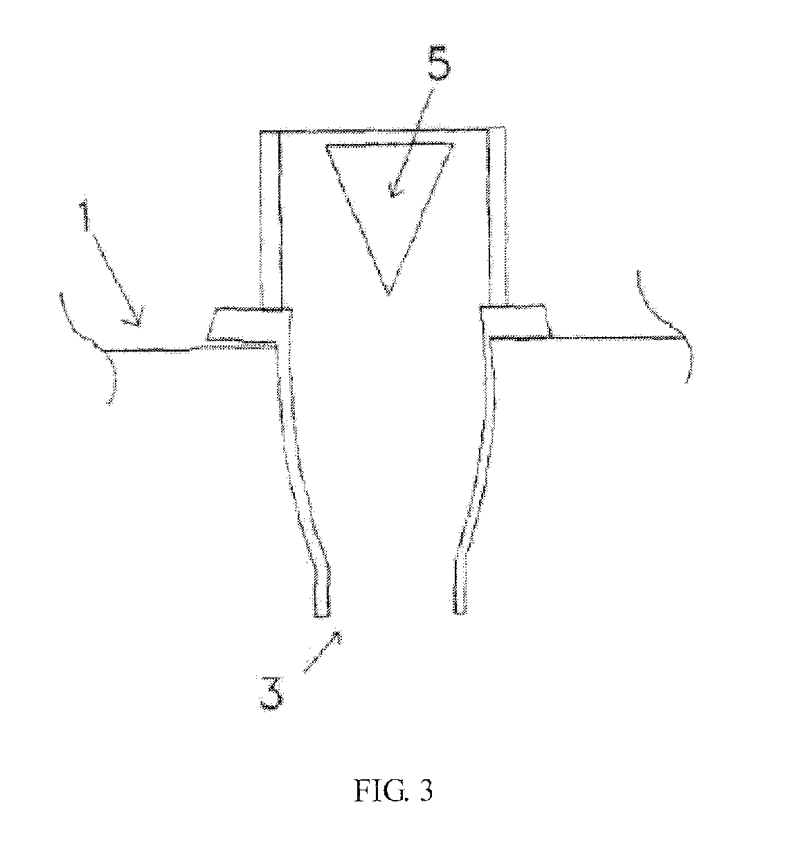
[0016]As shown in FIG. 3, similar to embodiment 1, the extension pipe section has several vertical inverted conical water inflow slots 5 evenly distributed on its periphery.

[0017]The water spraying nozzle for cooling tower described in the present invention comprises a nozzle body and / or an upper connection section of nozzle, depending on the structure of the water spraying nozzles.


PUM


Abstract

A water spray nozzle (3) for cooling tower is provided. Wherein, the nozzle (3) or the upper connection section of the nozzle (3) has an upward extension section in a water distribution groove (1). Several layers of water inlet holes or slots (4) are opened around the extension section at different heights, or several tapered water inlets (5) with downward taper tips are distributed around the extension section. The nozzle (3) far from a water distribution port can still get the uniformly distributed water even when the water quantity of the cooling tower is low, the efficiency of the cooling tower thereby will not be reduced.

Description

FIELD OF THE INVENTION [0001]The present invention relates to an improvement of nozzles for cooling tower, in particular to a self-adapting water spraying nozzle for cooling tower, which can regulate the water inflow automatically as the water yield varies.BACKGROUND OF THE INVENTION[0002]An important guarantee for the cooling effect of a cooling tower is even spraying of cooling water to the water spraying filler in the cooling tower. A water spraying approach in cooling tower is implemented with numerous non-pressure water spraying nozzles 3 with the same aperture 2, which are evenly distributed on the bottom of a water distribution channel 1 (as shown in FIG. 1); even water distribution from the nozzles is a prerequisite for even water spraying on the entire cross section and high water spraying efficiency. In the troughing distribution channel, the incoming water is distributed from the middle part towards the two ends of the channel, when the water inflow is relatively low (e.g...

Claims


Application Information

Patent Timeline
IPC IPC(8): A62C31/02
CPCB05B1/00F28F25/06B05B1/185
Inventor NING, FANGLIANGZHANG, HONGXINGNING, SHANGCHAO
Owner WUXI YONGXIN ENERGY TECH
Why Eureka
Try Eureka