Cam shaft phase variable device in engine for automobile

a technology of phase variable device and cam shaft, which is applied in the direction of valve arrangement, machines/engines, mechanical equipment, etc., can solve the problems of high cost of manufacturing these gears at high precision, large gear rattle, and high cost of reverse rotary mechanism of rotary drum (guide plate) 24. achieve the effect of low cost and easy manufacturing of torque means

Inactive Publication Date: 2013-12-24
NITTAN VALVE CO LTD
View PDF53 Cites 2 Cited by
  • Summary
  • Abstract
  • Description
  • Claims
  • Application Information

AI Technical Summary

Benefits of technology

[0058]When the second control rotor can rotate 360 degrees, the shaft of the first control rotor can reciprocate from one end of the radial guide slit to the other end, undergoing rotations in both the phase advancing direction and retarding directions relative to the drive rotor. In other words, the second brake means and second control rotor can independently rotate the first control rotor both in the phase advancing and phase retarding directions, thereby advancing or retarding the phase angle of the camshaft in either direction relative to the crankshaft.
[0059]In the camshaft phase variable device of claims 1 and 2 the torque means of the first control rotor can widen the variable range of phase angle of the camshaft relative to the crankshaft without reducing the torque of the first control rotor provided by the second control rotor. Since the elements of the torque means are of generally circular configuration, the torque means can operate calmly during a phase angle variation. Further, the torque means can be manufactured easily at low cost.

Problems solved by technology

The device of Patent Document 1 has a drawback in that the reverse rotary mechanism of the rotary drum (guide plate) 24 is not only costly but also presents gear noise.
The cost of manufacturing these gears at high precisions is disadvantageously high.
Further, operation of the planetary gear mechanism 25 involving many gears generate a large gear rattle, especially when the valve timing is varied.

Method used


Image

  • Cam shaft phase variable device in engine for automobile
  • Cam shaft phase variable device in engine for automobile
  • Cam shaft phase variable device in engine for automobile

Examples


first embodiment

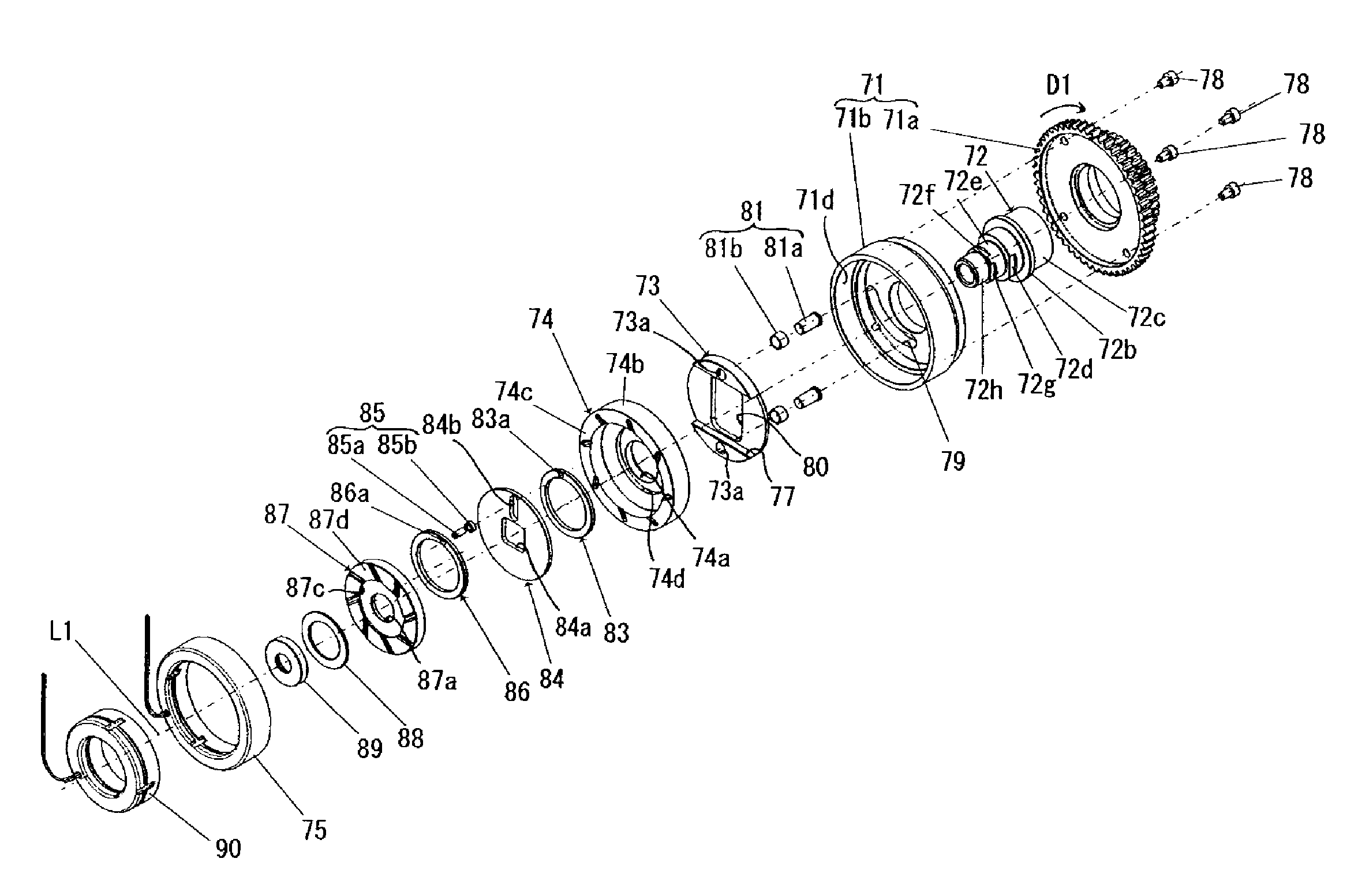
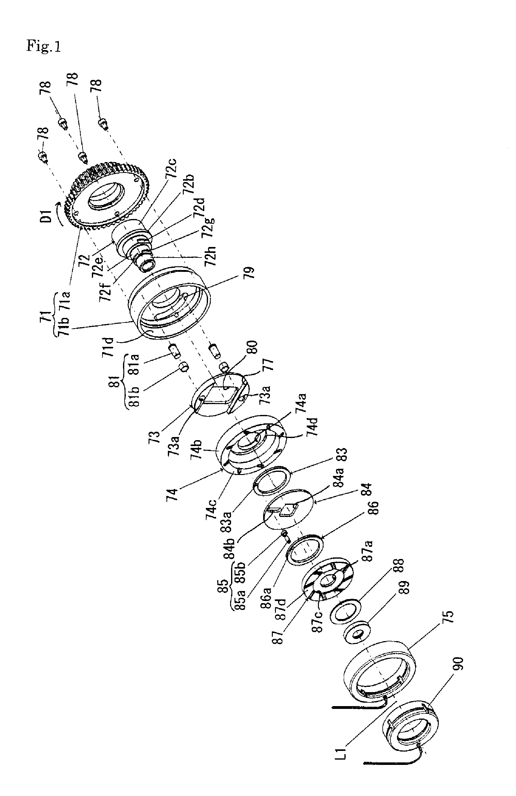
[0064]FIG. 1 is an exploded perspective view of a camshaft phase variable device for automobile engine in accordance with the invention, as seen from the front.

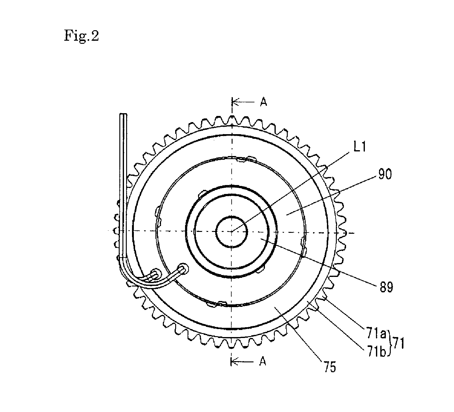
[0065]FIG. 2 is a front view of the device.

[0066]FIG. 3 shows an axial cross section of the device taken along line A-A of FIG. 2.

[0067]FIG. 4 shows radial cross sections of the device having no phase change, taken at different axial positions. More particularly, Fig. (a) shows a cross section taken along line B-B, Fig. (b) the cross section taken along line C-C, and Fig. (c) the cross section taken along line D-D of FIG. 3.

[0068]FIG. 5 shows cross sections of the device after a phase change, taken along the same lines as in FIG. 4.

[0069]FIG. 6 shows radial cross sections of the device having no phase change. More particularly, Fig. (a) shows the cross section taken along line E-E of FIG. 3, Fig. (b) cross section taken along line F-F of FIG. 3, and Fig. (c) cross section taken along line G-G.

[0070]FIG. 7 shows cross sections...

second embodiment

[0071]FIG. 8 is a cross sectional view of the camshaft phase variable device in accordance with the second embodiment, the figure taken along line G-G of FIG. 3 to show the first ring member and the first circular eccentric hole.

[0072]FIG. 9(a) shows a cross section of the camshaft phase variable device in accordance with the third embodiment taken along line E-E of FIG. 3, showing the second ring member and the second circular eccentric hole of the device. FIG. 9(b) shows a cross section of the camshaft phase variable device in accordance with the third embodiment taken along line G-G of FIG. 3, showing the first ring member and the first circular eccentric hole.

[0073]In use the camshaft phase variable device of the invention is installed integral with an engine. The device is adapted to transmit the rotational motion of the crankshaft to a camshaft so as to open / close an intake valve / exhaust valve and to vary the valve timing of the intake valve / exhaust valve in accordance with su...


PUM


Abstract

[PROBLEMS]
To provide an inexpensive cam shaft phase variable device of an engine in which the displacement width of attachment angle between a crankshaft and a camshaft is large and operational sound is silent.
[MEANS FOR SOLVING PROBLEMS]
In a phase variable device of an engine for altering the phase angle between a cam shaft and crankshaft depending on the relative rotational direction of a first control body of revolution being braked by a rotary operating force imparting means, the rotary operating force imparting means comprises a brake means of the first control body of revolution, a second intermediate body of revolution rotating synchronously with the cam shaft, a second control body of revolution having a brake means, a first eccentric rotating mechanism interlocked with the first control body of revolution to perform eccentric rotation, a second eccentric rotating mechanism interlocked with the second control body of revolution to perform eccentric rotation, and a means for coupling the first and second eccentric rotating mechanisms to perform relative rotation by engaging with the substantially radial guide groove of the second intermediate body of revolution under displaceable state.

Description

TECHNICAL FIELD[0001]This invention relates to an automobile phase varying device equipped with a camshaft and a torque means for rotating a rotary drum in the forward or backward direction relative to the coaxial camshaft to advance or retard the rotational phase of the camshaft relative to the crankshaft of the automobile engine, thereby changing the valve timing of the engine. The relative rotational direction of the camshaft to advance / retard the phase angle thereof will be referred to phase advancing / retarding direction.BACKGROUND ART[0002]There has been known a valve timing control device as disclosed in Patent Document 1 cited below. Patent Document 1 discloses a device for varying the phase angle of the camshaft 1 of an internal combustion engine relative to the drive plate 2 driven by the crankshaft of the engine, in the phase advancing direction (which is the same as the rotational direction of the driving plate 2) or phase retarding direction (which is opposite to the rot...

Claims


Application Information

Patent Timeline
Patent Type & Authority Patents(United States)
IPC IPC(8): F01L1/34
CPCF01L1/352F01L2001/3522F01L1/34F01L1/344
Inventor KAMEDA, MICHIHIRONAGADO, MASAYASU
Owner NITTAN VALVE CO LTD
Why Eureka
Try Eureka