

Photographing optical lens assembly
a technology of optical lens and assembly, applied in the field of compact optical lens assembly, can solve the problem that the conventional four-leaf lens assembly does not meet the specification of the high-level photographing lens assembly
- Summary
- Abstract
- Description
- Claims
- Application Information
AI Technical Summary
Benefits of technology
Problems solved by technology
Method used
Image

Examples
first embodiment (embodiment 1)
The First Embodiment (Embodiment 1)
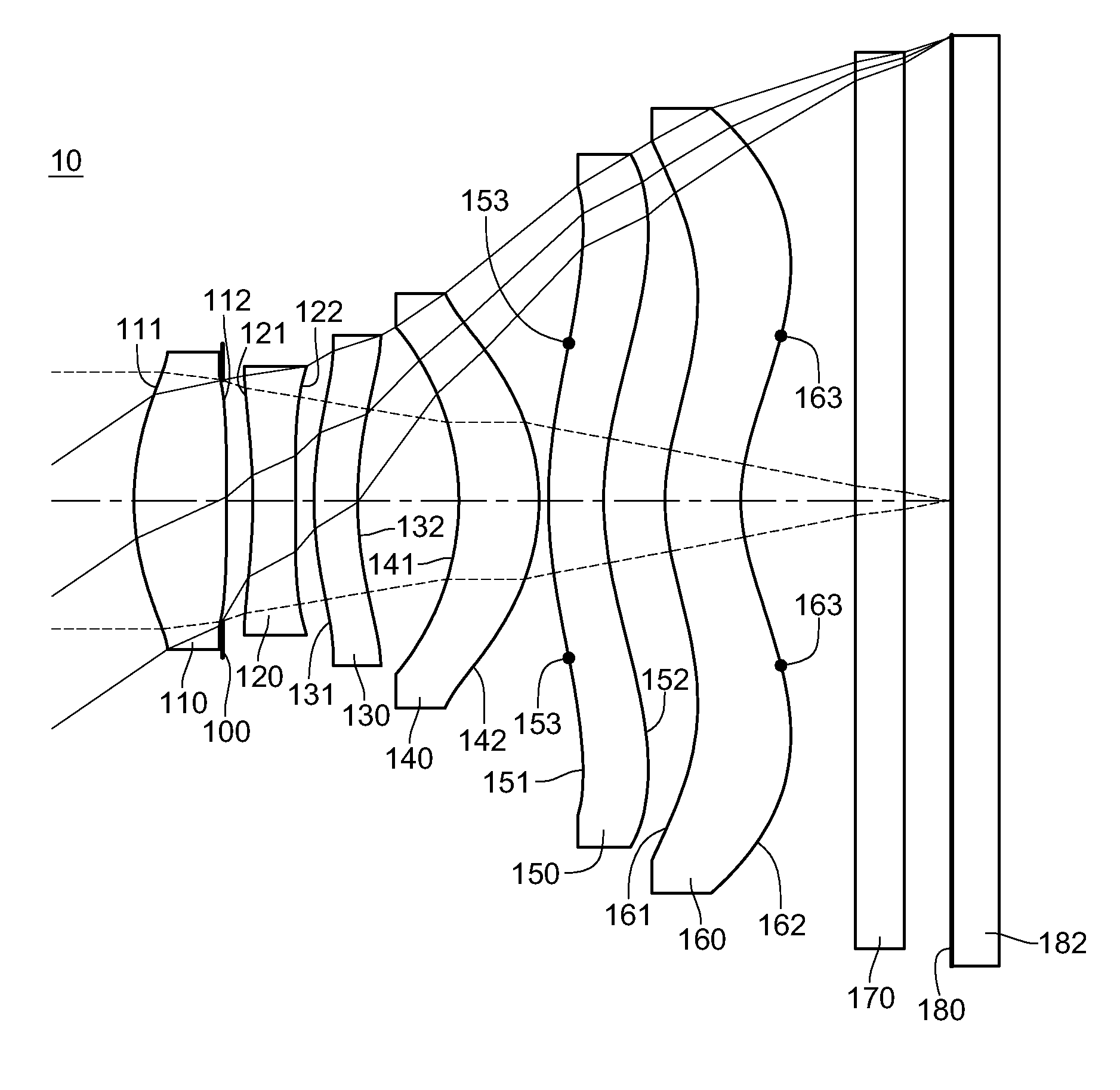
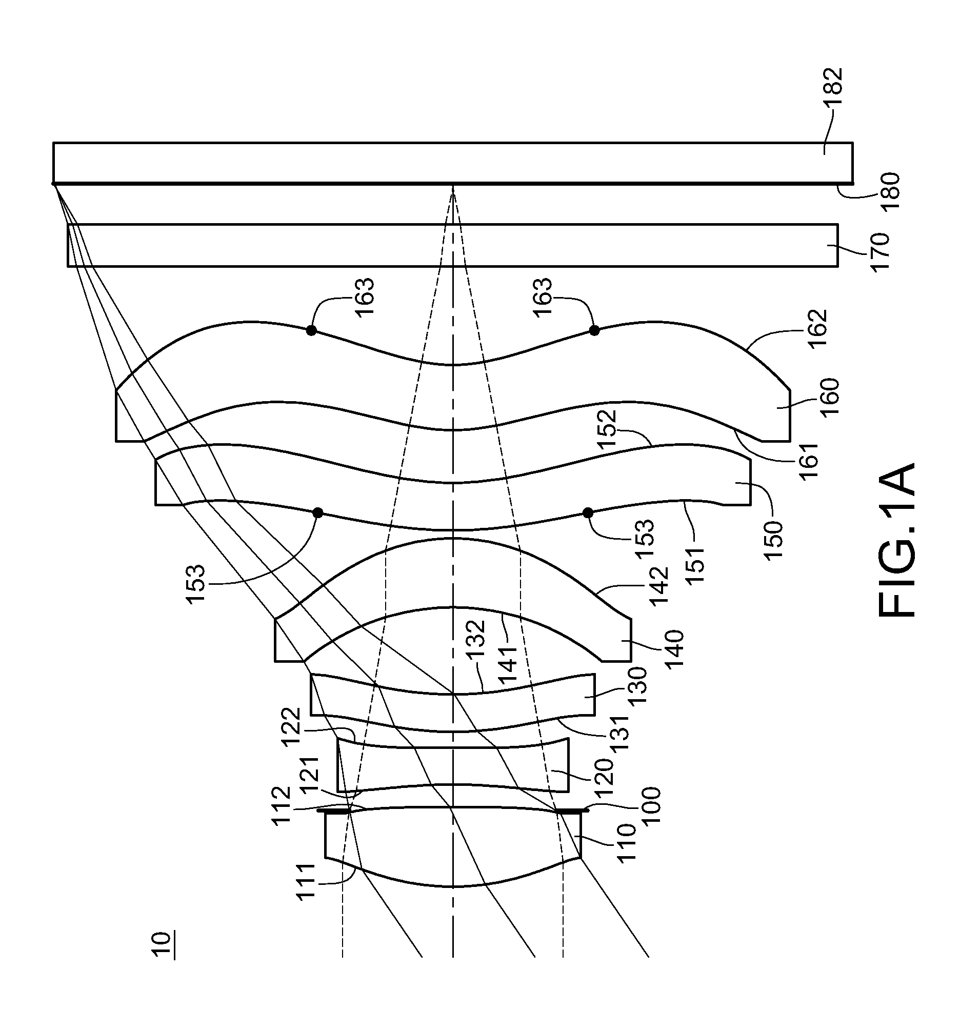
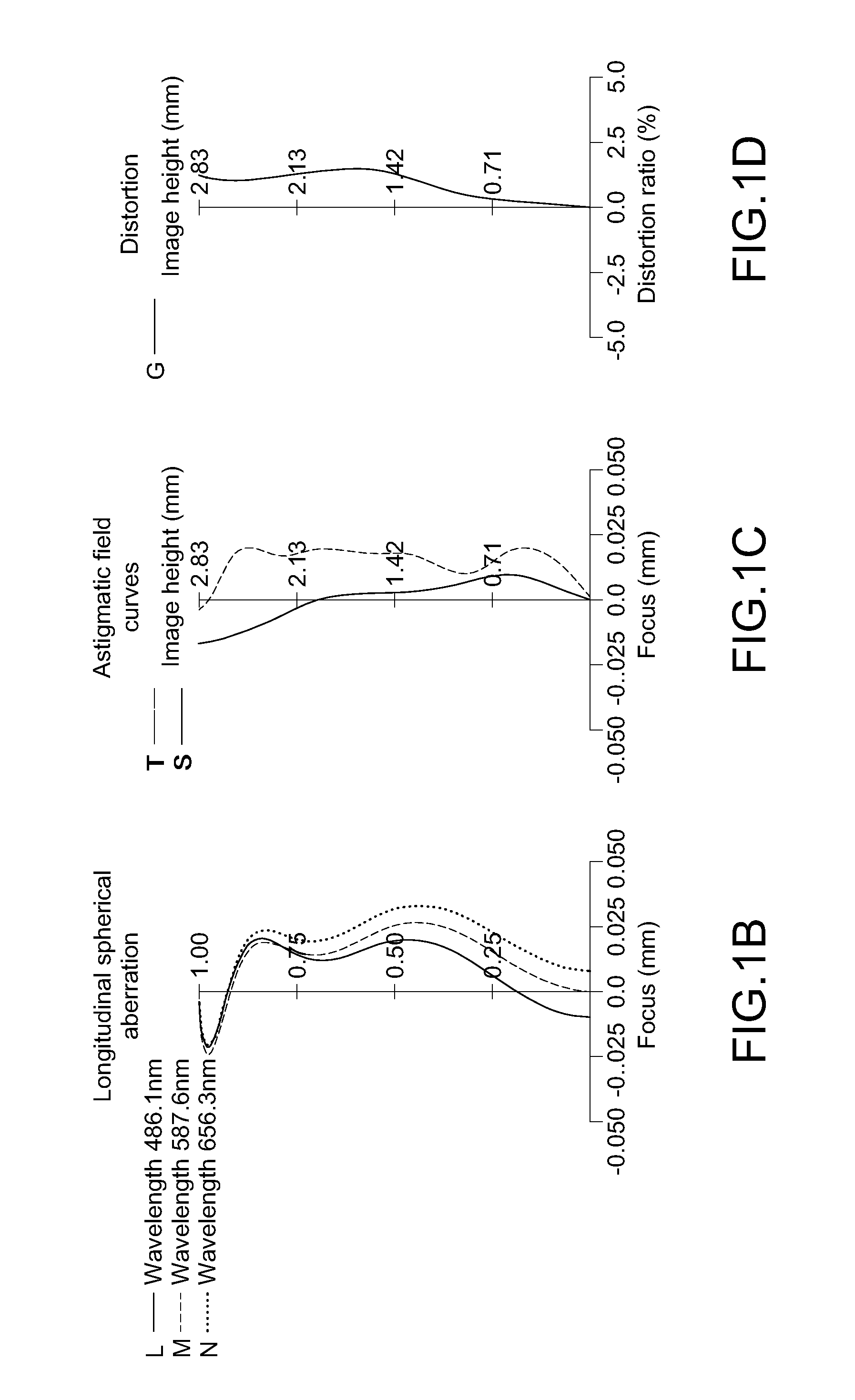
[0071]FIG. 1A is a schematic structural view of the first embodiment of the photographing optical lens assembly.
[0072]In this embodiment, the first lens element 110 with positive refractive power comprises the convex object-side surface 111. The second lens element 120 has negative refractive power. The third lens element 130 with positive refractive power comprises the concave image-side surface 132. The fourth lens element 140 with positive refractive power comprises the concave object-side surface 141 and the convex image-side surface 142. The fifth lens element 150 with negative refractive power comprises the convex object-side surface 151, the concave image-side surface 152, and the inflection points 153. The sixth lens element 160 with negative refractive power comprises the convex object-side surface 161, the concave image-side surface 162, and the inflection points 163. The aperture stop 100 can be disposed between the first lens element 11...
second embodiment (embodiment 2)
The Second Embodiment (Embodiment 2)
[0084]FIG. 2A is a schematic structural view of the second embodiment of the photographing optical lens assembly. The specific implementation and elements of the second embodiment are substantially the same as those in the first embodiment. The element symbols in the second embodiment all begin with “2” which correspond to those in the first embodiment with the same function or structure. For conciseness, only the differences are illustrated below, and the similarities will not be repeated herein.
[0085]In this embodiment, for example, the wavelength of the light received by the photographing optical lens assembly 20 is 587.6 nm, but this wavelength may be adjusted according to actual requirements, and is not limited to the wavelength value mentioned above.
[0086]In this embodiment, a first lens element 210 with positive refractive power comprises a convex object-side surface 211. A second lens element 220 has negative refractive power. A third lens...
third embodiment (embodiment 3)
The Third Embodiment (Embodiment 3)
[0093]FIG. 3A is a schematic structural view of the third embodiment of the photographing optical lens assembly. The specific implementation and elements of the third embodiment are substantially the same as those in the first embodiment. The element symbols in the third embodiment all begin with “3” which correspond to those in the first embodiment with the same function or structure. For conciseness, only the differences are illustrated below, and the similarities will not be repeated herein.
[0094]In this embodiment, for example, the wavelength of the light received by the photographing optical lens assembly 30 is 587.6 nm, but the wavelength may be adjusted according to actual requirements, and is not limited to the wavelength value mentioned above.
[0095]In this embodiment, a first lens element 310 with positive refractive power comprises a convex object-side surface 311. A second lens element 320 has negative refractive power. A third lens elem...
PUM
 Abstract
Description
Claims
Application Information