Photographic Synchronization Optimization System and Method

a technology of synchronizing optimization and photo synchronization, applied in the direction of shutters, exposure control, instruments, etc., can solve the problems of unfavorable synchronization of flash lighting at greater shutter speeds, and unfavorable photo synchronization

a technology of synchronizing optimization and photo synchronization, applied in the direction of shutters, exposure control, instruments, etc., can solve the problems of unfavorable synchronization of flash lighting at greater shutter speeds, and unfavorable photo synchronization

US20120243859A1Active Publication Date: 2012-09-27LAB PARTNERS ASSOC INC

Image

  • Photographic Synchronization Optimization System and Method
  • Photographic Synchronization Optimization System and Method
  • Photographic Synchronization Optimization System and Method

Examples


Embodiment Construction

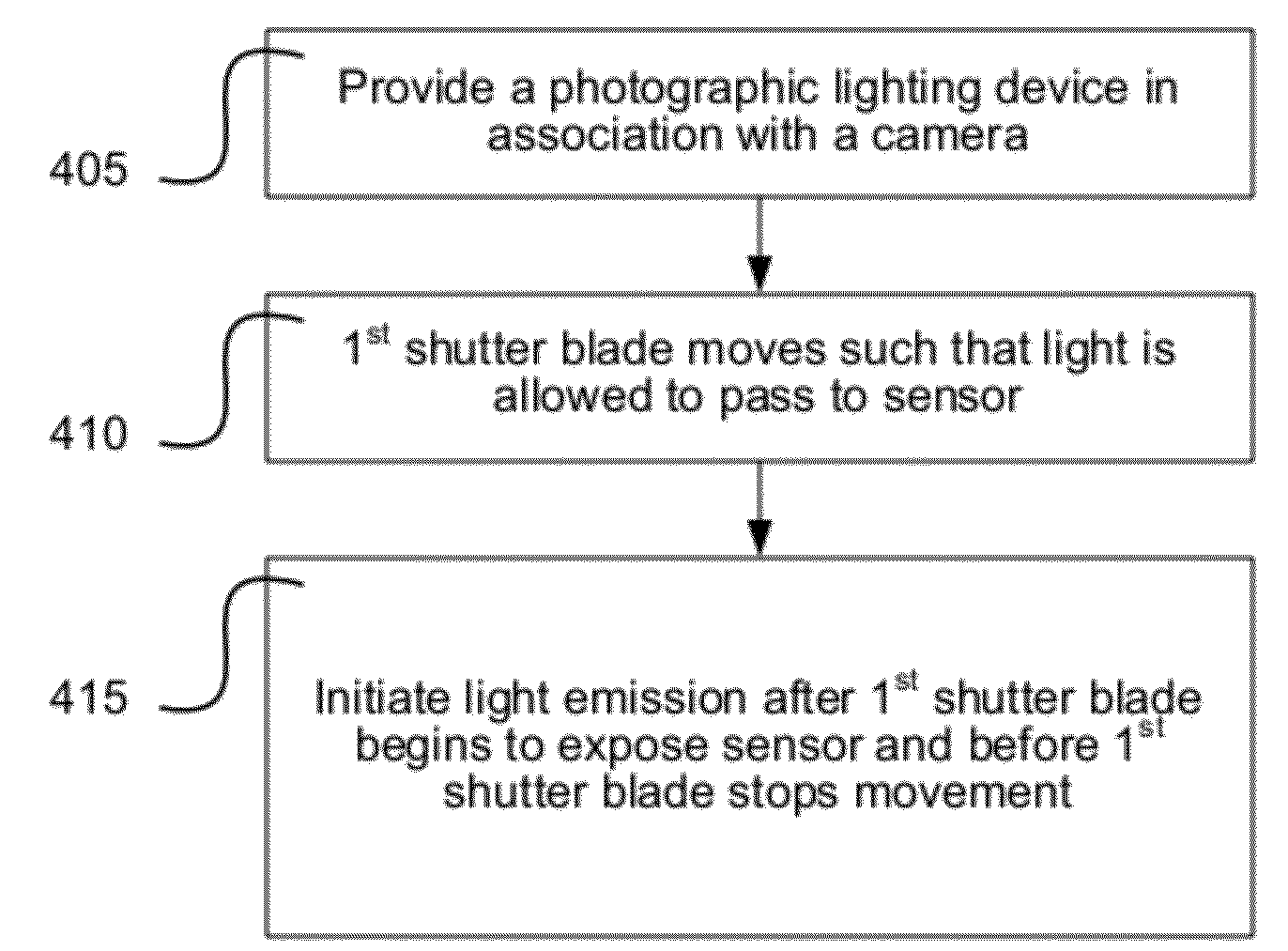
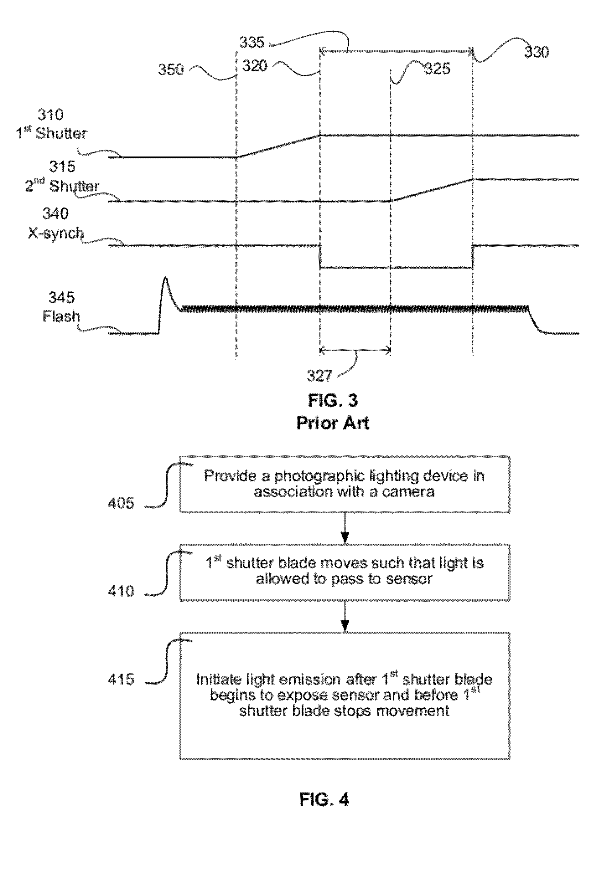
[0080]A system and method for synchronizing a photographic lighting device to image acquisition by a camera is provided. In one embodiment, light emission by one or more lighting devices is initiated after a first shutter blade movement of a camera begins to allow light to pass from the camera lens to an imaging sensor of the camera and before X-sync associated with the completion of the first shutter blade movement.

[0081]As discussed above, there may be some additional movement of the first shutter blade after the normal temporal location for initiation of X-sync. When discussing completion of the first shutter blade movement with respect to the timing of photographic light emission in embodiments of the current disclosure, the stopping of movement being referred to is that of the point of the normal initiation of X-sync for the camera. If there is subsequent movement of the shutter blade, it is not considered in determining the time at which the first shutter blade stops movement ...


PUM


Abstract

A system and method for synchronizing a photographic lighting device to image acquisition by a camera using light emission profile information to position a light emission profile at a desired location in an image acquisition window. A light energy balance point of a light emission profile can be used to position the balance point at a desired location in an image acquisition window.

Description

RELATED APPLICATION DATA[0001]This application is a continuation-in-part of U.S. patent application Ser. No. 13 / 208,686, filed Aug. 12, 2011, and titled “Early Photographic Critical Point Synchronization System and Method,” which is a continuation of International Application No. PCT / US2010 / 024088, filed Feb. 12, 2010, and titled “Early Photographic Synchronization System and Method,” each of which is incorporated by reference herein in its entirety. This application also claims the benefit of priority of U.S. Provisional Patent Application Ser. No. 61 / 444,784, filed Feb. 20, 2011, and titled “Photographic Synchronization Optimization System and Method” and U.S. Provisional Patent Application Ser. No. 61 / 152,089, filed Feb. 12, 2009, and titled “Early Photographic Synchronization System and Method,” each of which is incorporated by reference herein in its entirety.[0002]This application is also related to commonly-owned and co-pending U.S. patent application Ser. No. 13 / 201,281 enti...

Claims


Application Information

Patent Timeline
27 Sep 2012
Publication
US20120243859A1
IPC
G03B9/00
CPC
G03B9/40; G03B15/05; G03B2215/0557; G03B7/16; H05B41/32; G03B9/70
Inventors
CLARK, JAMES E.