Printer, printing system and computer-readable meduim having instructions for printing

a printing system and printing instruction technology, applied in printing, inking apparatus, etc., can solve problems such as degradation of print quality, and achieve the effect of improving print quality and reducing the cost of printers

Active Publication Date: 2012-10-04
SINFONIA TECHNOLOGY CO LTD
View PDF3 Cites 0 Cited by
  • Summary
  • Abstract
  • Description
  • Claims
  • Application Information

AI Technical Summary

Benefits of technology

[0016]With the program, only if the printer carries out energization based on the ink energization data received from the computer, thermal transfer of the ink is carried out, and only if the printer carries out correction of the laminate energization data received from the computer with the correction data and carries out energization based on the corrected laminate energization data, thermal transfer with the residual heat quantity of the thermal head taken into consideration can be carried out. Consequently, the necessity to incorporate a high speed arithmetic operation unit such as a DSP (Digital Signal Processor) into the printer is eliminated, and the cost of the printer can be reduced.
[0017]With the printer, printing system and computer program, the correction section corrects laminate energization data using correction data for correcting laminate energization data in response to a residual heat quantity. Therefore, the laminate material can be thermally transferred with the laminate energization data corrected with the residual heat quantity of the thermal head after the ink is thermally transferred taken into consideration. Consequently, the print quality can be improved.

Problems solved by technology

In other words, even if the thermal head, that is, the heat generating resistive element, is energized in accordance with energization data or pulse data for thermally transferring the laminate material, a desired amount of the laminate material may not be transferred, resulting in degradation of the print quality.

Method used


Image

  • Printer, printing system and computer-readable meduim having instructions for printing
  • Printer, printing system and computer-readable meduim having instructions for printing
  • Printer, printing system and computer-readable meduim having instructions for printing

Examples


Embodiment Construction

[0024]In the following, a printing system to which the present invention is applied is described with reference to the accompanying drawings.

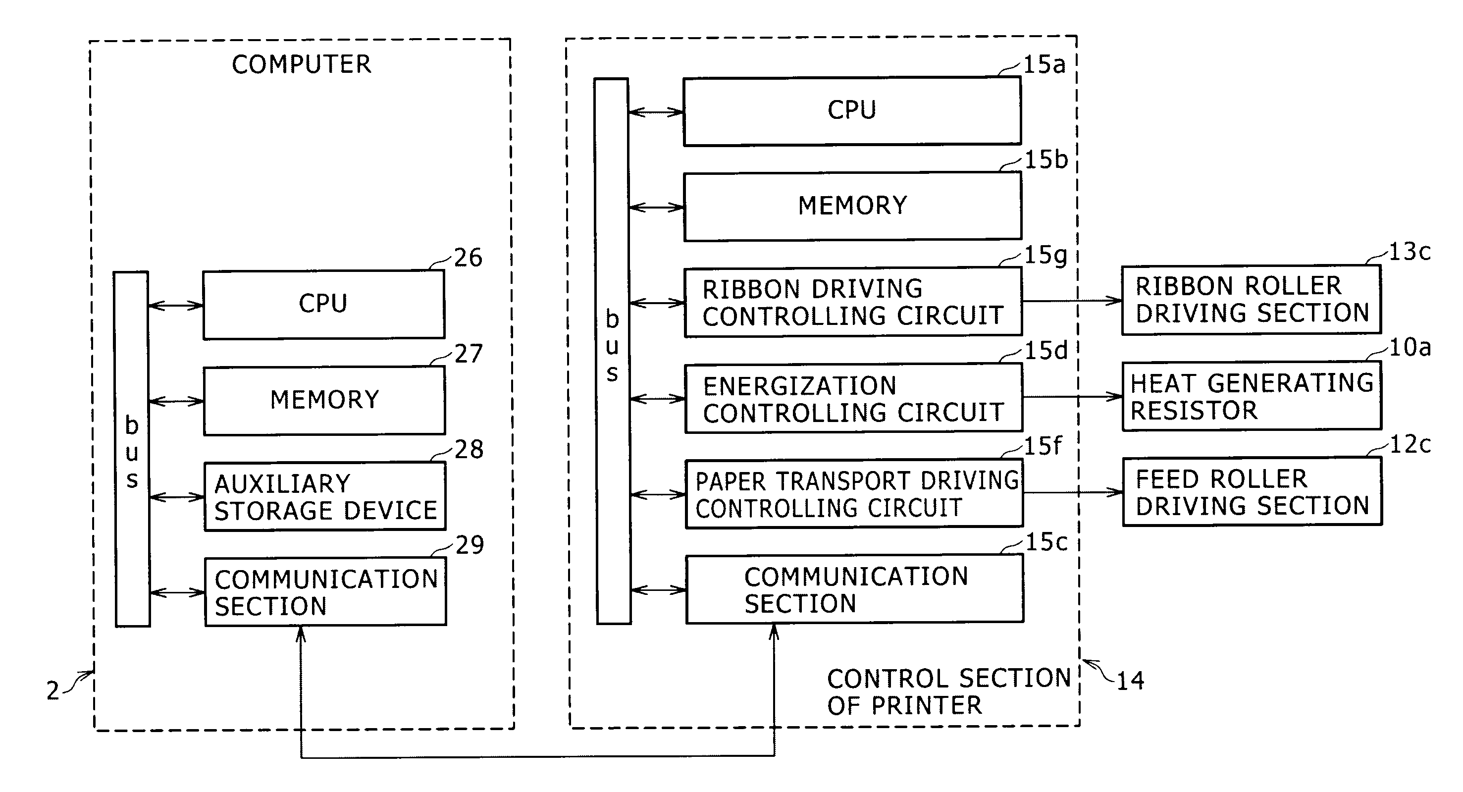
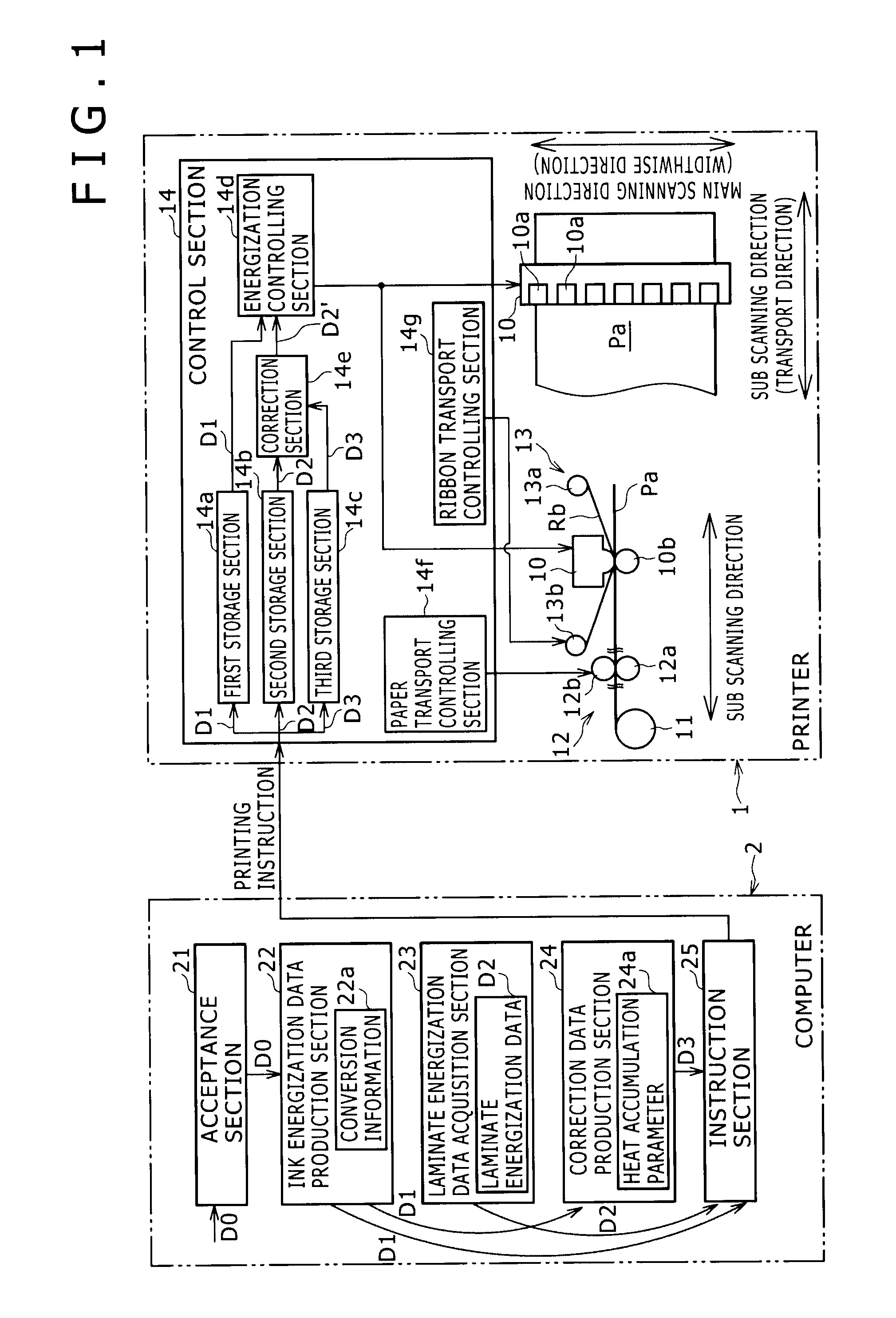
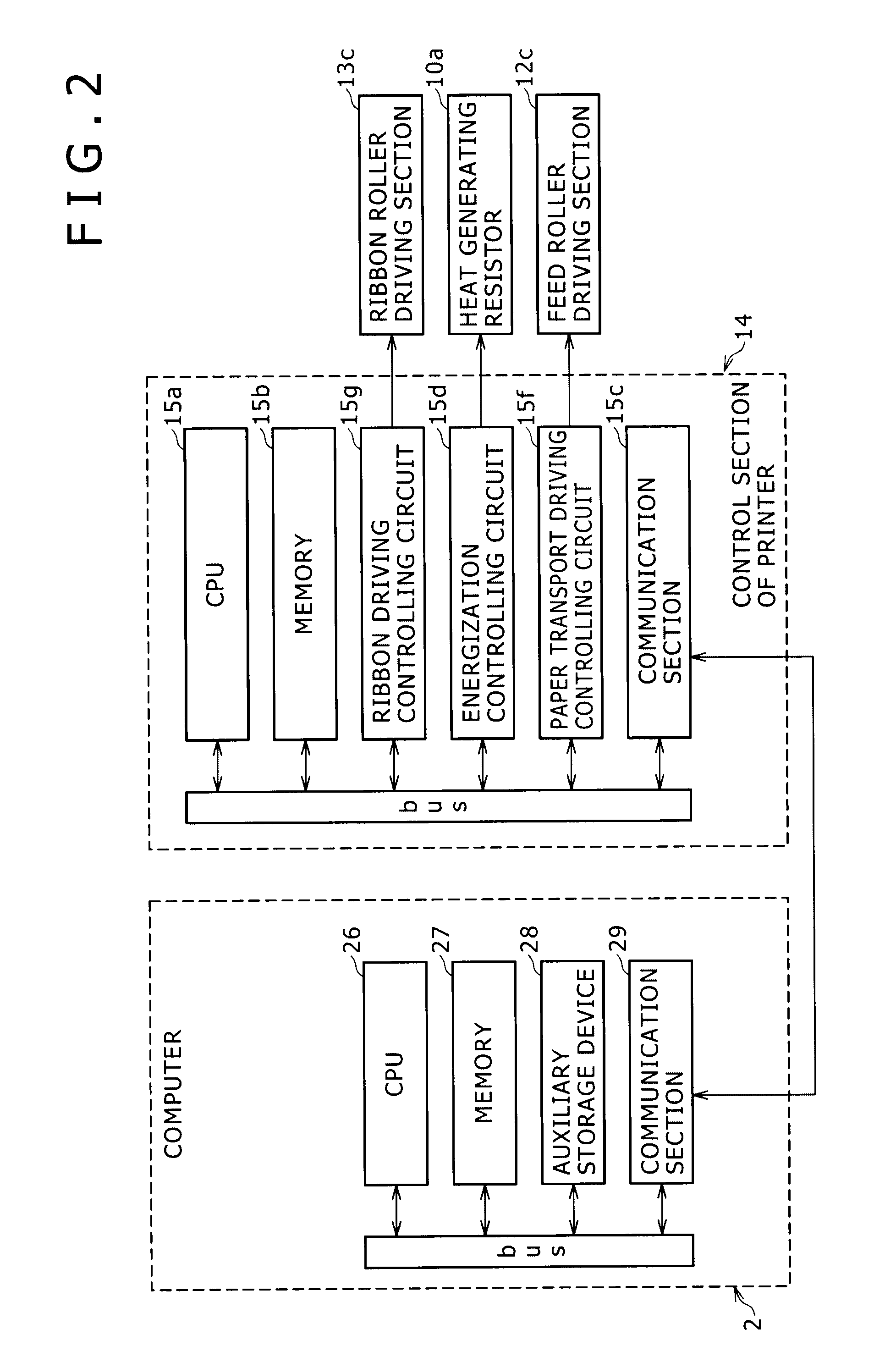
[0025]Referring first to FIGS. 1 and 2, the printing system shown includes a printer 1, and a computer 2 configured for communication with the printer 1 for instructing the printer 1 to carry out thermal transfer.

[0026]Referring particularly to FIG. 1, the printer 1 includes a thermal head 10 on which a plurality of heat generating resistive elements 10a which generate heat when they are energized are disposed such that they configure one line, and a paper supplying section 11 which holds a recording medium Pa such as a paper roll so as to be supplied. The printer 1 further includes a paper transport section 12 for transporting the recording medium Pa, a ribbon transport section 13 for supplying a ribbon Rb to the thermal head 10, and a control section 14 for controlling driving of the functional blocks 10 to 13. Thus, in the printer 1, the rib...


PUM


Abstract

A printer having a ribbon heated by energization of a thermal head to transfer color ink and transparent laminate material from the ribbon to a recording medium. The printer includes a first storage section configured to store ink energization data, a second storage section configured to store laminate energization data an energization controlling section, and a correction section that corrects the laminate energization data in response to a residual heat quantity of the thermal head after the ink is thermally transferred in accordance with stored ink energization data and corrects the laminate energization data.

Description

CROSS REFERENCE TO RELATED APPLICATION[0001]This application claims priority to Japanese Application Numbers 2011-079967, filed on Mar. 31, 2011, and 2012-068932, filed on Mar. 26, 2012, the entire contents of which are hereby incorporated by reference.BACKGROUND OF THE INVENTION[0002]1. Field of the Invention[0003]This invention relates to a printer, a printing system and a computer program for heating a ribbon by energization of a thermal head to thermally transfer a thermal transfer object of the ribbon such as color ink and transparent laminate material to a recording medium such as paper.[0004]2. Description of the Related Art[0005]An exemplary printer of the thermal transfer type is disclosed in Japanese Patent laid-Open No. 2000-15886. In the printer, a ribbon to which a transfer object including a plurality of inks or dyestuffs of different colors is applied is transported together with a recording medium such as paper in a state in which the ribbon is pressed against the re...

Claims


Application Information

Patent Timeline
Patent Type & Authority Applications(United States)
IPC IPC(8): B41J2/00
CPCB41J2202/33B41J2/355
Inventor MATSUDA, KOICHI
Owner SINFONIA TECHNOLOGY CO LTD
Why Eureka
Try Eureka