Imaging device, imaging method, and computer readable storage medium

Inactive Publication Date: 2012-10-04
FUJIFILM CORP
View PDF2 Cites 5 Cited by
  • Summary
  • Abstract
  • Description
  • Claims
  • Application Information

AI Technical Summary

Benefits of technology

[0009]The present invention was made in order to overcome the above-described problems, and an object thereof is to provide an imaging device, an imaging method and a computer readable storage medium that can precisely detect fluorescent samples in a wide dynamic range, even in a subject in which fluorescent samples are arrayed in a two-dimensional form.
[0011]An imaging method relating to a sixth aspect of the present invention includes: lighting all of a plural light source elements that illuminate a subject, and pre-exposing the subject; on the basis of a pre-exposure image of the subject that is picked-up by an image pick-up element, that picks-up an image of the subject, due to the pre-exposure, specifying a saturated region that is saturated when exposed for an exposure time of actual exposure; specifying a light source element that corresponds to the saturated region, on the basis of the relationships of correspondence between the plural light source elements and regions that are illuminated by the plural light source elements respectively; and carrying out actual exposure by shortening a lighting time of the specified light source element.
[0012]According to a seventh aspect of the present invention, in a computer readable storage medium storing a program that causes a computer to execute an imaging method, the imaging method includes: lighting all of a plurality of light source elements that illuminate a subject, and pre-exposing the subject; on the basis of a pre-exposure image of the subject that is picked-up by an image pick-up element, that picks-up an image of the subject, due to the pre-exposure, specifying a saturated region that is saturated when exposed for an exposure time of actual exposure; specifying a light source element that corresponds to the saturated region, on the basis of the relationships of correspondence between the plurality of light source elements and regions that are illuminated by the plurality of light source elements respectively; and carrying out actual exposure by shortening a lighting time of the specified light source element.

Problems solved by technology

In such an imaging device, when imaging fluorescent samples having a broad range of fluorescent intensities, there is the problem that, even if exposure is carried out for a short time, regions where the fluorescent intensity is strong become saturated, and conversely, regions where the fluorescent intensity is weak cannot be sufficiently detected.
However, the technique disclosed in above-described JP-A No. 2003-232733 has the problem that it cannot be applied in cases in which fluorescent samples are arrayed in a two-dimensional form.

Method used


Image

  • Imaging device, imaging method, and computer readable storage medium
  • Imaging device, imaging method, and computer readable storage medium
  • Imaging device, imaging method, and computer readable storage medium

Examples


Embodiment Construction

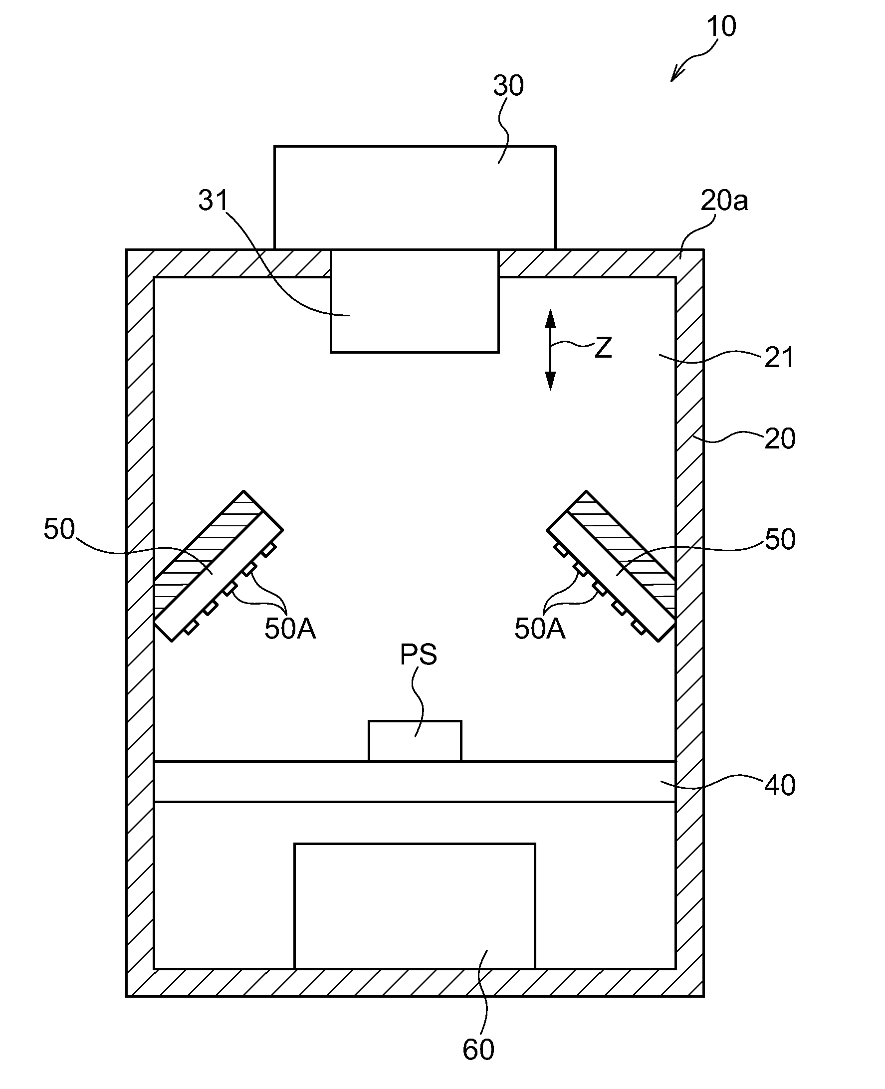
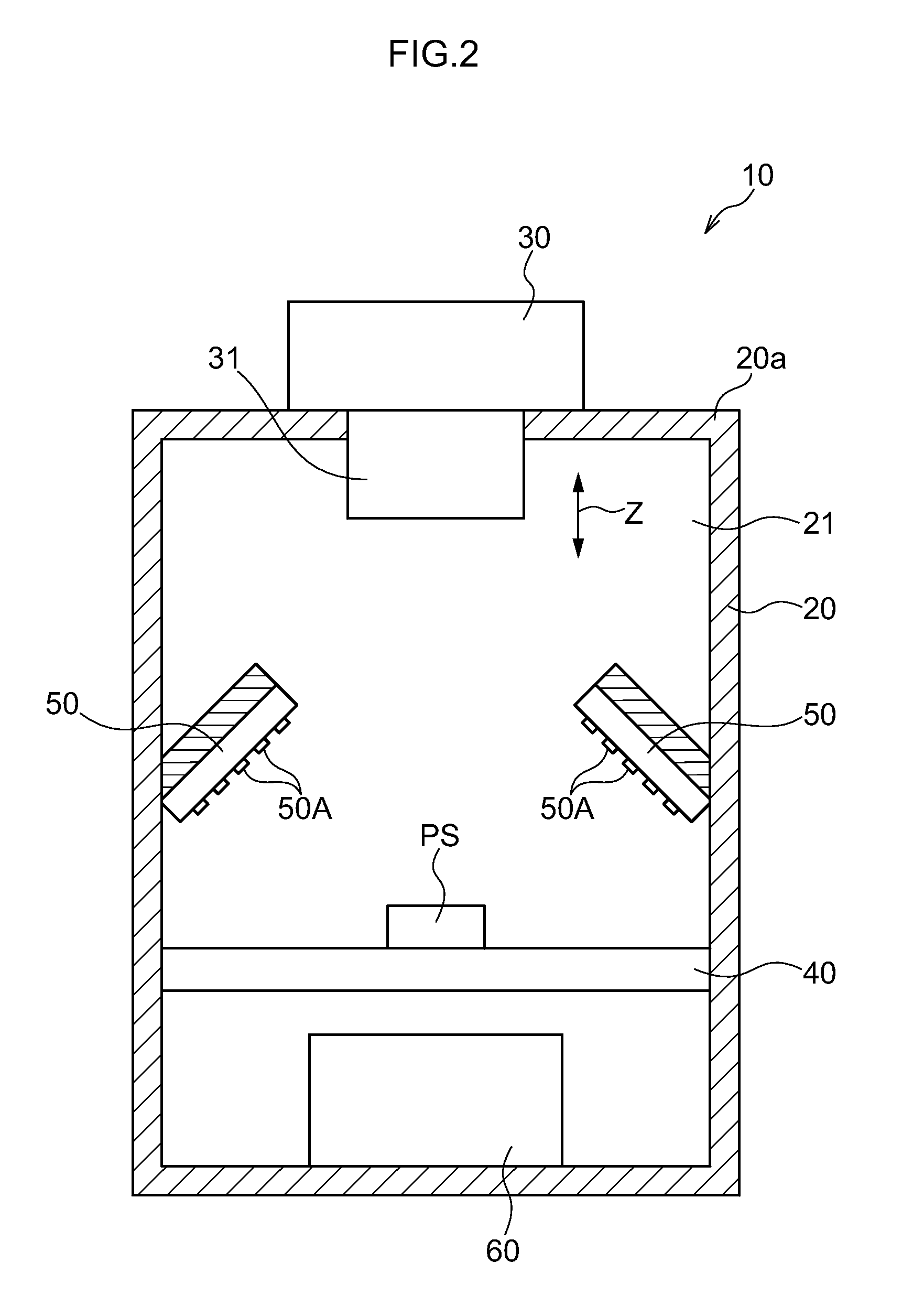
[0021]An exemplary embodiment of the present invention is described hereinafter with reference to the drawings.

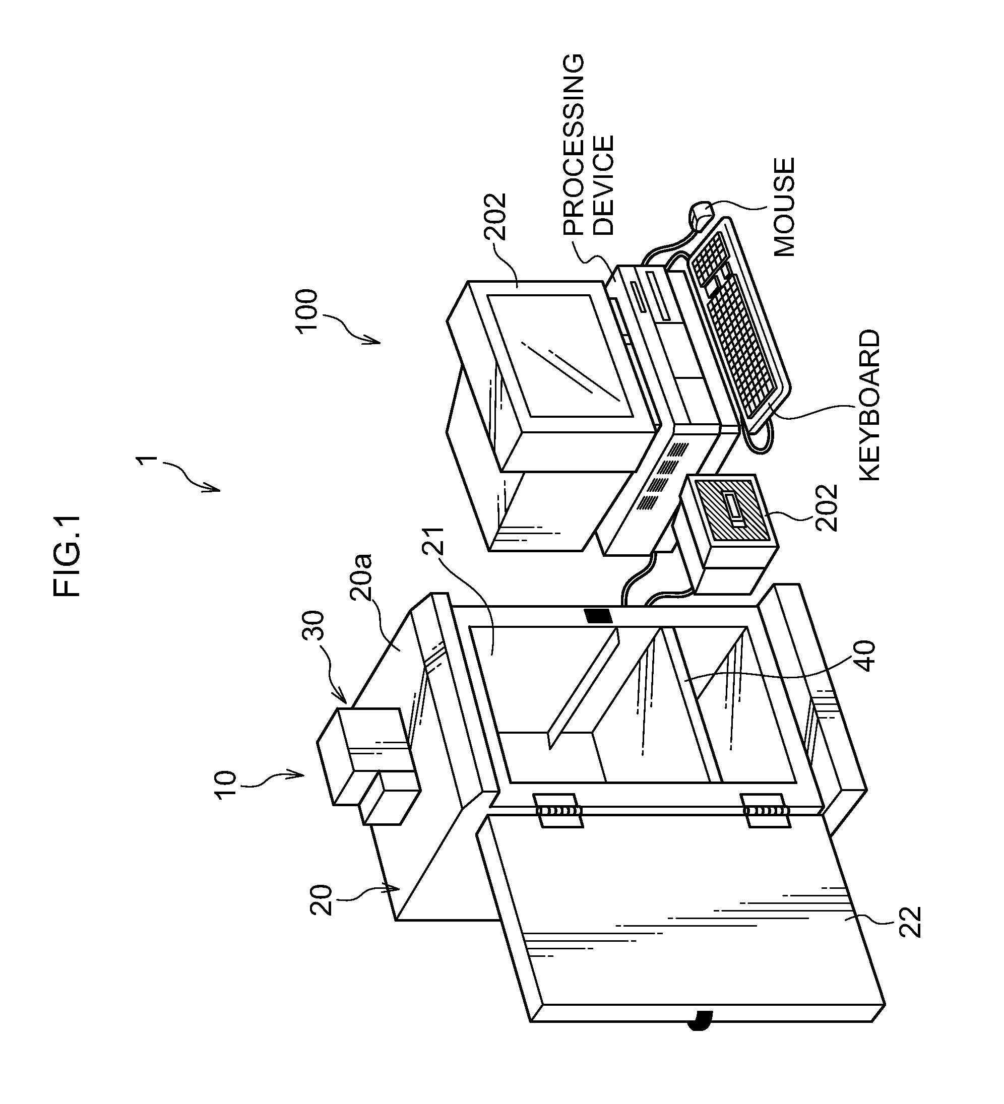
[0022]FIG. 1 is a perspective view showing an example of an imaging system that uses an imaging device relating to the present invention. An imaging system 1 is an imaging system that images a subject without illuminating excitation light or by illuminating excitation light in accordance with the subject, and acquires a captured image of the subject. The imaging system 1 is structured to include an imaging device 10 and an image processing device 100.

[0023]The imaging device 10 outputs, to the image processing device 100, image data of the subject that is obtained by imaging the subject. The image processing device 100 subjects the received image data to predetermined image processings as needed, and displays the image data on a display 202.

[0024]Note that the subject may be, for example, the aforementioned chemiluminescent sample, or may be a fluorescent sample, but is not...


PUM


Abstract

There is provided an imaging device that has: light source elements that illuminate a subject; an image pick-up element that picks-up an image of the subject; storage unit that stores relationships of correspondence between the light source elements and regions that are illuminated by the light source elements respectively; pre-exposure unit that lights all of the light source elements and pre-exposing the subject; specifying unit that, on the basis of a pre-exposure image of the subject that is picked-up by the image pick-up element due to the pre-exposure, specifies a saturated region that is saturated when exposed for an exposure time of actual exposure; and actual exposure unit for, on the basis of the relationships of correspondence, specifies a light source element that corresponds to the saturated region, and carries out actual exposure by shortening a lighting time of the specified light source element.

Description

CROSS-REFERENCE TO RELATED APPLICATION[0001]This application is based on and claims priority under 35 USC 119 from Japanese Patent Application No. 2011-072917 filed on Mar. 29, 2011, which is incorporated by reference herein.BACKGROUND[0002]1. Technical Field[0003]The present invention relates to an imaging device, an imaging method and a computer readable storage medium, and in particular, relates to an imaging device, an imaging method and a computer readable storage medium having cooling means for cooling an image pick-up element.[0004]2. Related Art[0005]In the field of biochemistry for example, there has conventionally been proposed an imaging device that picks-up, as a subject, a fluorescent sample that emits fluorescent light due to excitation light being illuminated and is labeled by a fluorescent dye, or picks-up, as a subject, a chemiluminescent sample that contacts a chemiluminescent substrate and emits light (see, for example, Japanese Patent Application Laid-Open (JP-A)...

Claims


Application Information

Patent Timeline
IPC IPC(8): H04N5/235
CPCG01N21/253G01N21/6452G01N21/6456H04N5/2354G03B15/07H04N5/2351G03B7/28H04N23/71H04N23/74
Inventor MAKINO, KAZUHIRO
Owner FUJIFILM CORP
Why Eureka
Try Eureka