
Compensating for periodic nonuniformity in electrophotographic printer

Inactive Publication Date: 2012-10-04
EASTMAN KODAK CO
View PDF2 Cites 35 Cited by
  • Summary
  • Abstract
  • Description
  • Claims
  • Application Information

AI Technical Summary

Benefits of technology

[0039]An advantage of this invention is that it compensates for periodic non-uniformities using direct measurements of the imaging components causing the non-uniformities. This reduces error in the compensation due to shifts in the phase of the artifacts. Since compensation can be performed for any phase relationship between the rotating component(s) and the print images, the printer has more flexibility in terms of what print modes it can employ. Various embodiments compensate for variations in nip spacing, even when the spacing is varying in a complicated manner. Measuring individual imaging components deconfounds the effects introduced by each component and permits determining the compensation for each effect individually.

Problems solved by technology

Various components used in the electrophotographic process, such as belts and drums, can have mechanical or electrical characteristics that result in periodic objectionable non-uniformities in print images, such as streaks (extending in-track) or bands (extending cross-track).
Damped springs for mounting components can experience periodic vibrations, causing the spacing between the mounted components to change over time.
Paul describes that the phase of a periodic banding defect (an artifact extending cross-track) is difficult to measure because, unlike frequency, it varies from page to page.
Moreover, multiple components in a printer can have individual non-uniformities, which interact with each other.
This results in significant cross-correlation and noise in measured density data, which makes compensation more difficult.
Variations in the rotational frequency of components will also make it more difficult to extract each component's data from the measured data.

Method used


Image

  • Compensating for periodic nonuniformity in electrophotographic printer
  • Compensating for periodic nonuniformity in electrophotographic printer
  • Compensating for periodic nonuniformity in electrophotographic printer

Examples


Embodiment Construction

[0053]As used herein, the terms “parallel” and “perpendicular” have a tolerance of ±10°.

[0054]The term “variation” refers to a mechanical or electrical non-ideality or characteristic that has a negative effect on the image quality of a printed image, or on the ability of a printer to reproduce a desired aim image or density.

[0055]The terms “nonuniformity,”“defect,” and “artifact” refer to detectable or measurable errors in the reproduction by a printer of a given aim. For example, a banding artifact is a stripe that extends in the cross-track direction and that has a density or densities different than the aim density or densities in the stripe. The term “nonuniformity” refers to the fact that artifacts are generally detected using test targets that would be uniform in density, if not for the artifacts.

[0056]FIGS. 12A and 13A are halftoned representations of simulated image artifacts. FIGS. 12B and 13B show discrete Fourier transforms of columns of those images, with frequency on th...


PUM


Abstract

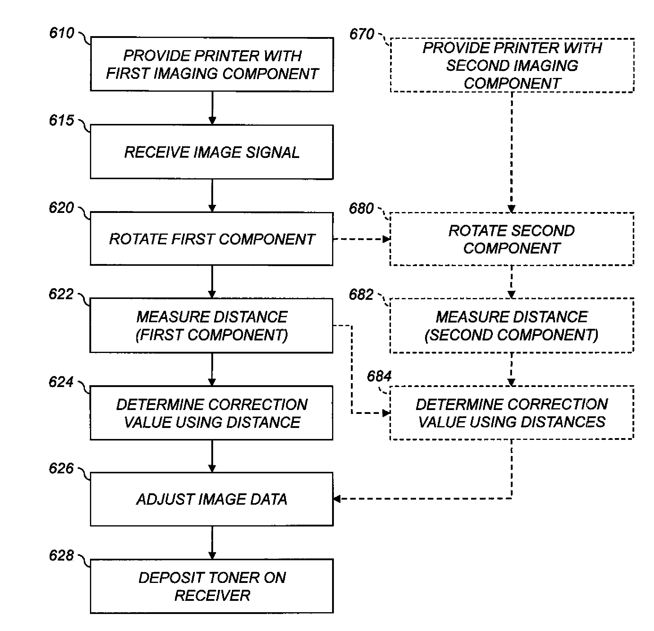
A method is provided of compensating for periodic non-uniformity in an electrophotographic (EP) printer with a rotatable imaging component, and a runout sensor for measuring the distance between a first reference point and the surface of the first component along a first reference axis. An image signal representing an image to be produced on a receiving member by the printer is received. The component is rotated. While it is rotating, the distance for the component is measured using the runout sensor. A correction value corresponding to the measured distance is automatically determined using a processor. The image data corresponding to the measured distance are automatically adjusted with the correction value using the processor. Toner corresponding to the adjusted image data is deposited on the receiver using the component.

Description

CROSS-REFERENCE TO RELATED APPLICATIONS[0001]Reference is made to commonly assigned, co-pending U.S. patent application Ser. No. ______, filed concurrently herewith, entitled “Determining The Cause of Printer Image Artifacts” by Thomas A. Henderson, et al., the disclosure of which is incorporated by reference herein.FIELD OF THE INVENTION[0002]This invention pertains to the field of electrophotographic printing and more particularly to compensating for nonuniformity in prints.BACKGROUND OF THE INVENTION[0003]Electrophotography is a useful process for printing images on a receiver (or “imaging substrate”), such as a piece or sheet of paper or another planar medium, glass, fabric, metal, or other objects as will be described below. In this process, an electrostatic latent image is formed on a photoreceptor by uniformly charging the photoreceptor and then discharging selected areas of the uniform charge to yield an electrostatic charge pattern corresponding to the desired image (a “lat...

Claims


Application Information

Patent Timeline
IPC IPC(8): G03G15/00
CPCG03G15/0178G03G15/5033G03G15/505G03G15/0194G03G2215/0478G03G2215/048G03G2215/0158
Inventor HENDERSON, THOMAS A.ALLEN, RICHARD G.
Owner EASTMAN KODAK CO
Learn More