Method and device for monitoring moving objects

a technology for moving objects and monitoring devices, applied in the field of monitoring objects, can solve problems such as the change of refractive index, the surface quality of bottles, and the limited reliability of the detection mechanism

Inactive Publication Date: 2012-10-11
OPTOSYS SA
View PDF2 Cites 18 Cited by
  • Summary
  • Abstract
  • Description
  • Claims
  • Application Information

AI Technical Summary

Benefits of technology

[0004]Accordingly, it is an object of the present invention to provide an improved monitoring method and monitoring device, which is comparatively simple and cost-efficient to realize and yet allows a highly reliable monitoring of the moving objects.
[0005]Relating to one preferred aspect of the monitoring method, the invention suggests that the light beam comprises light at a wavelength range that is substantially untransmittable through the section of an object, and that the presence of an object is determined on the basis of a transitional time period during which substantially no light within the untransmittable wavelength range is detected by the detector. Thus, a determination of the presence of an object at a certain position on the trajectory preferably relies on a detection of a complete cut-off of the light beam over the untransmittable wavelength range. This can greatly improve the reliability of the monitoring process and can be implemented in a cost-efficient manner.
[0006]According to another preferred aspect of the monitoring method, the absence of an object is determined on the basis of a transitional time period during which light within said untransmittable wavelength range is detected by said detector. Advantageously, an expected time may be provided for each of the objects to cross said light beam. Moreover, the absence of an object may be determined when light within said untransmittable wavelength range is detected by the detector during the expected time. In this way, not only the presence of an object during an arbitrary time may be determinable, but alternatively or additionally the absence of an object during its expected time. Advantageously, this can be employed to further improve the quality assurance during a production cycle.

Problems solved by technology

Due to the small magnitude of this effect, however, the reliability of the detection mechanism is limited.
Further limitations arise from the fact that the surface quality of the bottles often varies during one manufacturing phase or in between subsequent production cycles.
For instance, the side walls of the bottles are often lubricated with a soap solution after their cleaning which leads to a change of their refractive index.

Method used


Image

  • Method and device for monitoring moving objects
  • Method and device for monitoring moving objects

Examples


Embodiment Construction

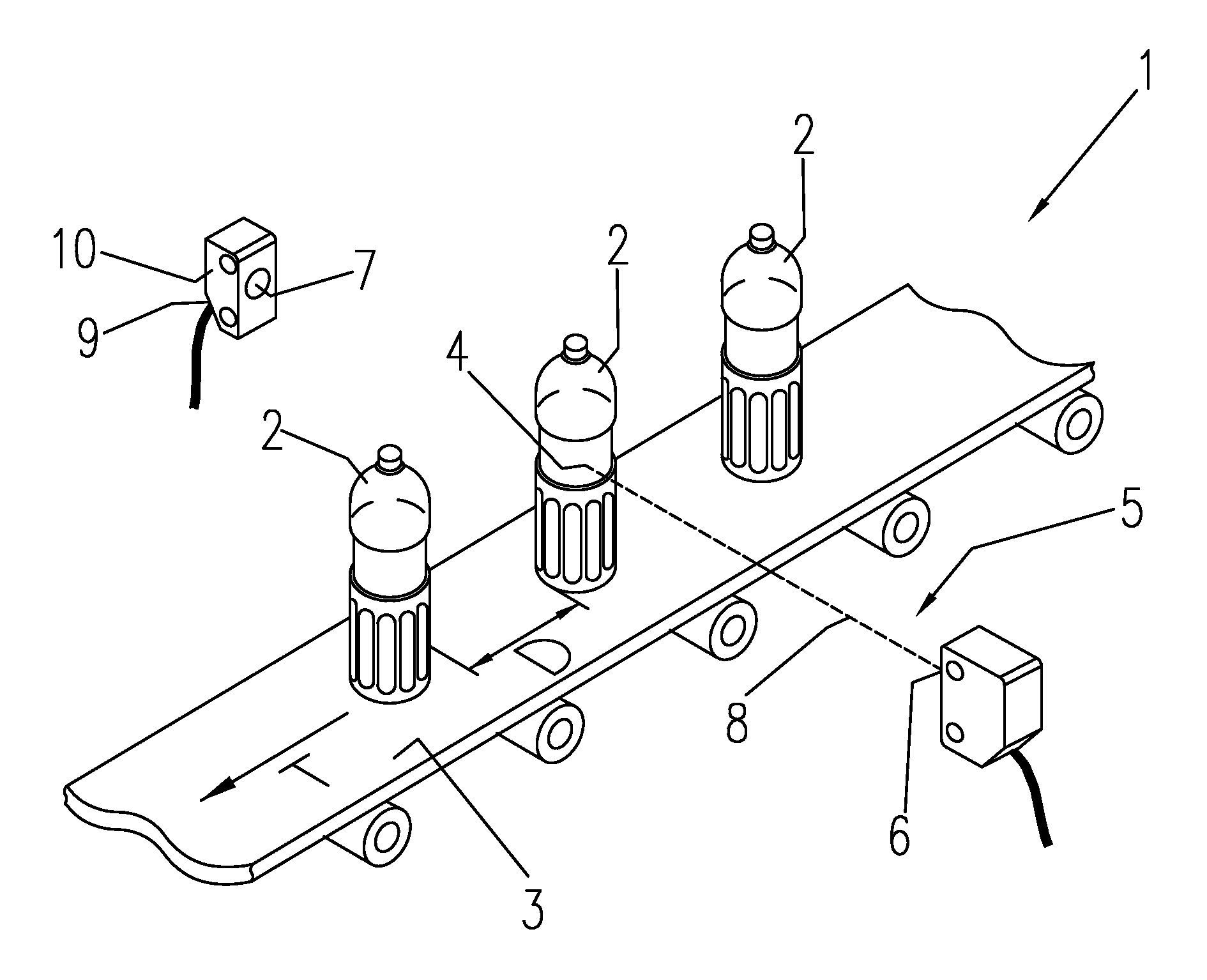
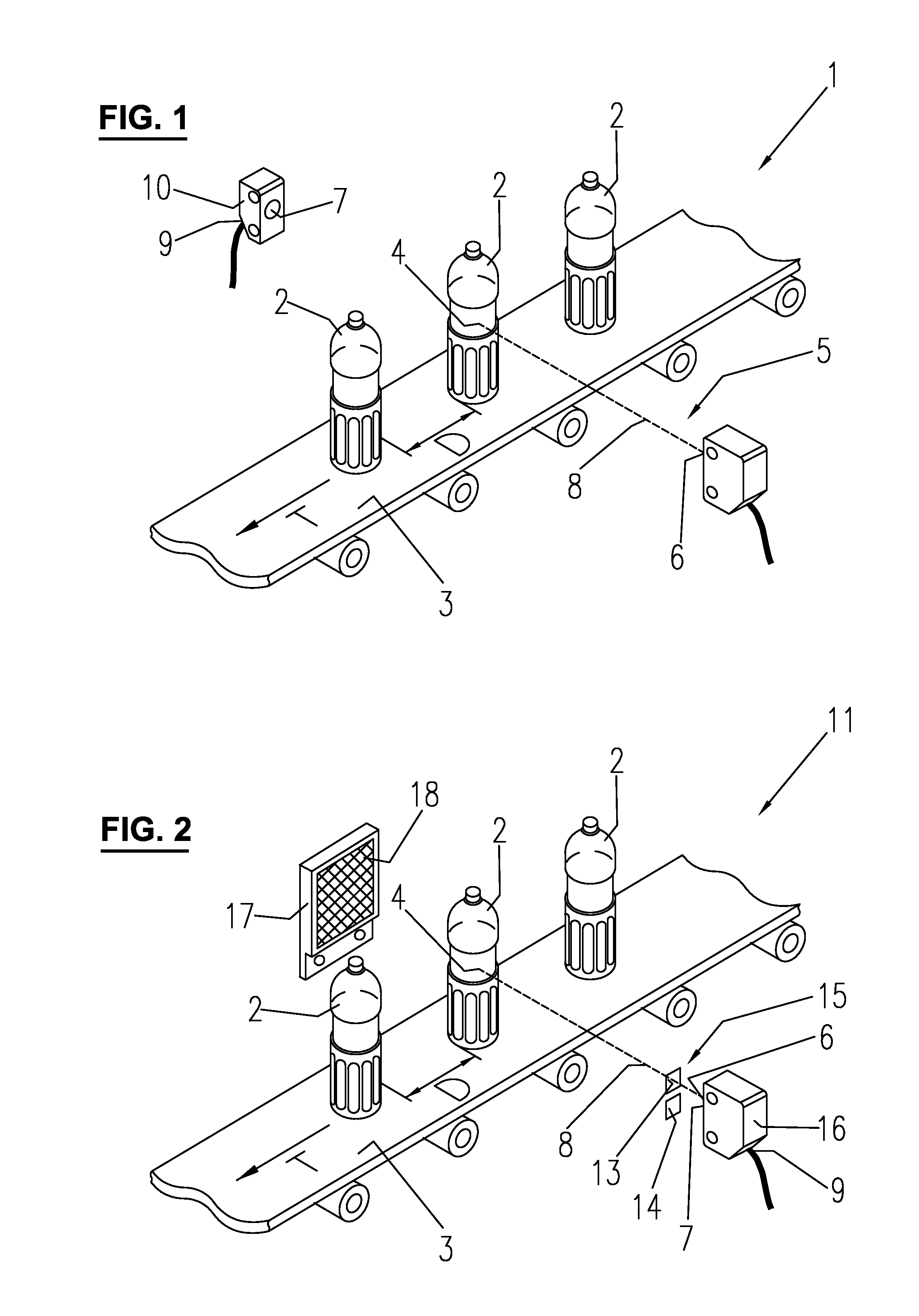
[0031]In the production line 1 shown in FIG. 1 empty bottles 2 are subsequently positioned on a conveyor belt 3 in an automatic process. The longitudinal extension of the conveyor belt 3 defines a trajectory T, along which the bottles 2 are moved with a relative distance D from each other. The walls of bottles 2 consist of a material that is transparent to visible light, for instance a soda-lime glass or PET.

[0032]The relative distance D depends on the frequency in which the receptacles 2 are placed on the conveyor belt 3 by the preceding automated process. In many applications, the relative distance D is ideally constant in between two subsequent bottles 2 and may correspond to an expected value. For quality assurance, however, it is necessary to verify the expected presence of a receptacle 2 at the predicted time interval in order to ensure a correct mode of operation of a subsequent process step, such as a filling service for the bottles. In other applications, the expected relat...


PUM


Abstract

A method and a device for monitoring objects moving along a trajectory. The objects include a section that is transparent or translucent. The objects subsequently cross a light beam at the section. The presence or absence of an object is determined during a transitional time period during which substantially no light or light within a wavelength range substantially untransmittable through the section is detected. A monitoring device generates an output signal based on the light detection indicating the presence or absence of an object.

Description

FIELD OF THE INVENTION[0001]The invention relates to a method for monitoring objects that are moved along a trajectory with a relative distance from each other, the objects comprising a section that is transparent or translucent in the visible light spectrum, wherein a light beam is directed transverse to the trajectory such that the objects subsequently cross the light beam at said section, and wherein light from the light beam is detected by a detector. The invention further relates to a monitoring device of a generic kind comprising a light emitter and a detector.BACKGROUND OF THE INVENTION[0002]Such a monitoring device and method is used, for instance, in a bottling line for glass bottles or PET bottles. Before or after an automatized filling of these bottles, they are often transported via a conveyor belt from or to another automatized processing step, such as cleaning, sealing, labeling or packaging. The subsequent processing step is usually synchronized with the preceding pro...

Claims


Application Information

Patent Timeline
Patent Type & Authority Applications(United States)
IPC IPC(8): G01J1/04
CPCG01V8/12B67C3/007G01V8/14G01N21/85G01V8/10
Inventor HEIMLICHER, PETERRHEME, CHARLES
Owner OPTOSYS SA
Why Eureka
Try Eureka