Video display apparatus

a video display and video technology, applied in the field of video display apparatus, can solve the problems of reducing the reliability of monitoring operation, complicating the process of arranging a plurality of screens, and difficult visual inspection, and achieve the effect of high reliability of monitoring and simple arrangemen

Inactive Publication Date: 2009-09-03
KOKUSA ELECTRIC CO LTD
View PDF11 Cites 1 Cited by
  • Summary
  • Abstract
  • Description
  • Claims
  • Application Information

AI Technical Summary

Benefits of technology

[0009]It is an object of the present invention to provide a video display apparatus which prevents video signals from being overlooked without using a complex and large-scale display means, thereby making it possible to offer a highly reliable monitoring service with a simpler arrangement.

Problems solved by technology

This may cause some important videos to be missed, and decrease the reliability of the monitoring operation.
In such conventional video display apparatus, however, the display screen must be divided into at least the number of screens which is obtained by multiplying the number of cameras with the number of events to be displayed, thereby complicating the process of arranging a plurality of screens.
Since the size of each screen is small, performing the visual check is also difficult.

Method used


Image

  • Video display apparatus
  • Video display apparatus
  • Video display apparatus

Examples


first embodiment

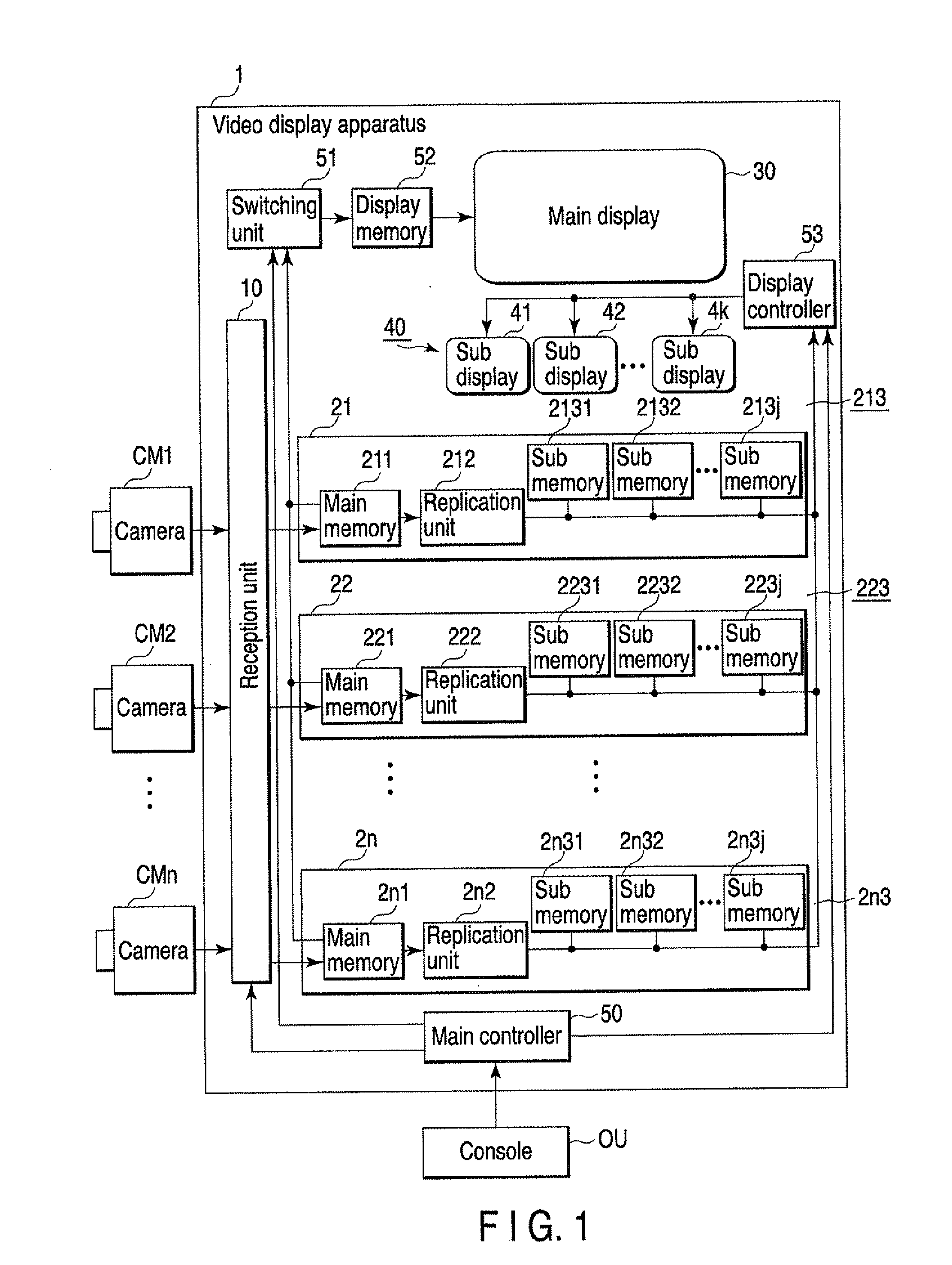
[0028]FIG. 1 is a block diagram showing the arrangement of a video display apparatus according to the first embodiment of the present invention. A video display apparatus 1 has a function of receiving video signals sent from a plurality of cameras CM1 to CMn set up at different positions, and displaying the received video signals. The video display apparatus 1 includes a reception unit 10, a plurality of storage units 21 to 2n provided in correspondence with the cameras CM1 to CMn, a main display 30, a sub-display unit 40, a plurality of sub-displays 41 to 4k, and a control unit. The sub-display unit 40 includes a plurality of sub-displays 41 to 4k. The control unit includes a main controller 50, switching unit 51, display memory 52, and display controller 53. Note that the main controller 50 and display controller 53 are implemented by causing a central processing unit (CPU) of a computer to execute application programs.

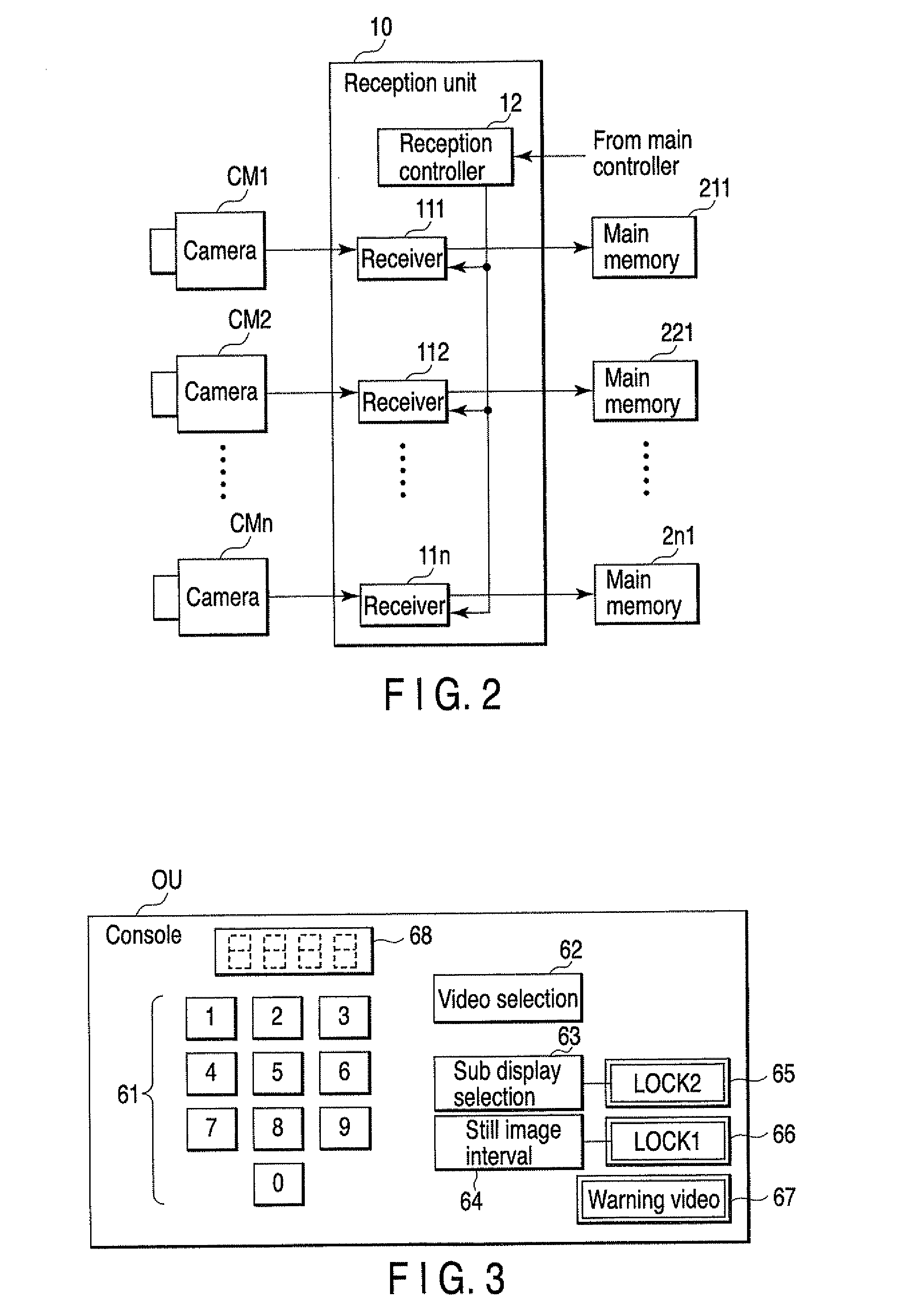
[0029]As shown in FIG. 2, for example, the reception unit 10 i...

second embodiment

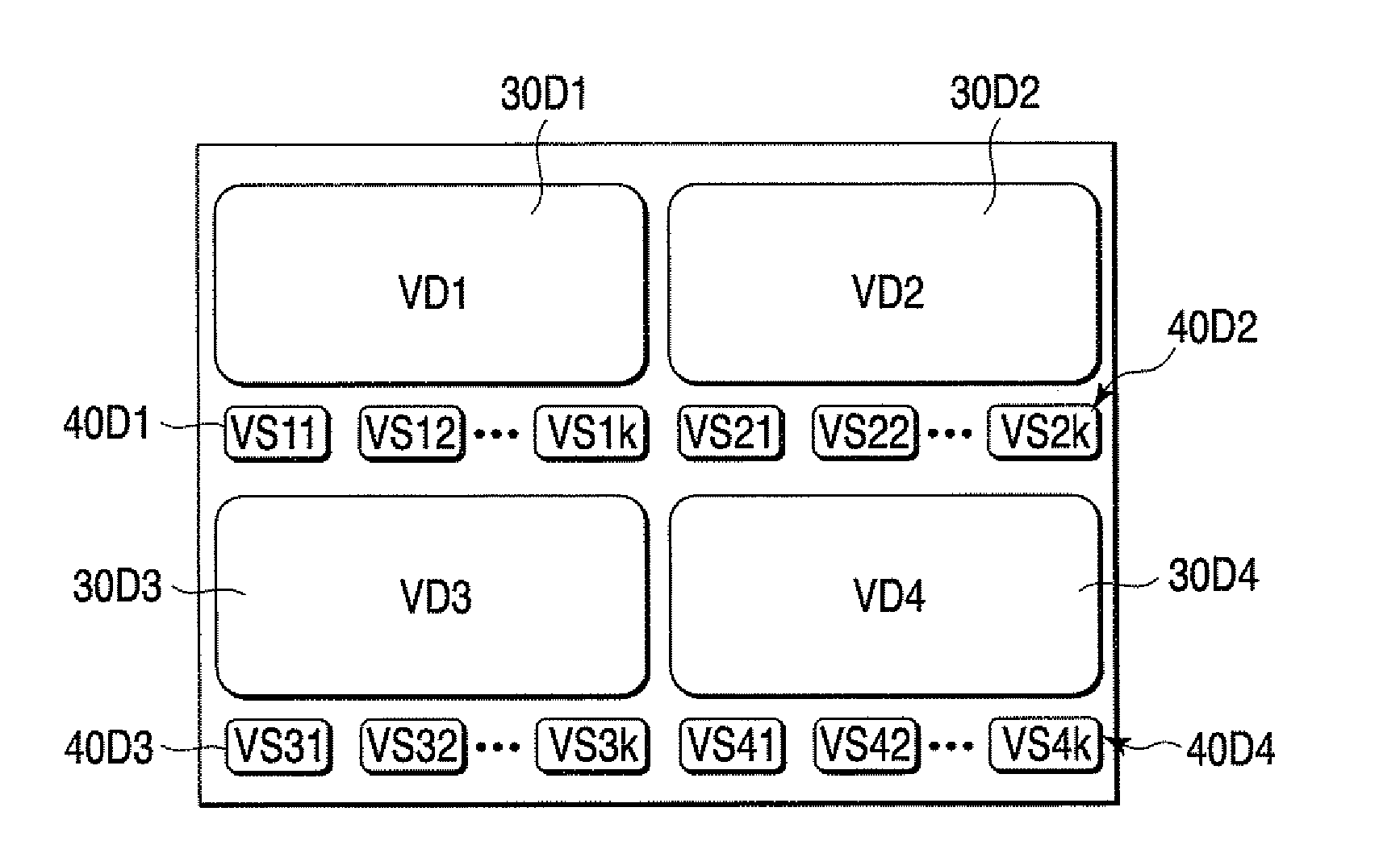
[0046]According to the second embodiment of the present invention, when still video VS1, VS2, or VS3 of an immediately preceding section which has not been displayed on a main display 30 is displayed on sub-displays 41 to 4k, the still video VS1, VS2, or VS3 is compared with a corresponding live video VD1, VD2, or VD3. If a difference larger than a predetermined amount is detected as a result of the comparison. On Screen Display data (OSD data) is generated, and corresponding still video data are added with the OSD data and then displayed.

[0047]FIG. 6 is a block diagram showing the functional arrangement of a display controller 54 provided for a video display apparatus 1 according to the second embodiment of the present invention. Note that the arrangements or functions of all the elements of the video display apparatus 1 other than the display controller 54 are the same as those of FIG. 1, and will be therefore described with reference to FIG. 1.

[0048]The display controller 54 of t...

third embodiment

[0056]In the first embodiment, the still videos of the non-displayed section of the live video VD1, VD2, or VD3 are displayed on the sub-displays 41 to 4k simultaneously with the display operation of the live video VD1, VD2, or VD3 on the main display 30. The present invention, however, is not limited to this. As shown in FIG. 8, for example, the still video data of the non-displayed section which are to be displayed on sub-displays 41 to 4k may be selected by the operation of the operator.

[0057]This can be done when the operator presses a sub-display selection button 63 of a console OU shown in FIG. 3. That is, the operator specifies / inputs the number of one of cameras CM1 to CMn through numeric keys 61, and then presses the sub-display selection button 63. With this operation, a main controller 50 instructs a display controller 53 to switch the display of the still video data. Consequently, the still video data displayed on the sub-displays 41 to 4k are switched to the videos VS21...


PUM


Abstract

A video display apparatus includes a reception unit configured to receive a plurality of sequence of video signals output from a plurality of cameras, a storage unit configured to store the plurality of sequence of video signals received by the reception unit, a display unit configured to include the first and second display areas, and a control unit. The control unit selectively and time-divisionally displays the plurality of sequence of video signals received by the reception unit on the first display area, and along with the display operation, selectively reads out from the storage unit a non-displayed section of the plurality of sequence of video signals which have been received by the reception unit, and displays the readout section on the second display area.

Description

CROSS-REFERENCE TO RELATED APPLICATIONS[0001]This application is based upon and claims the benefit of priority from prior Japanese Patent Application No. 2008-052457, filed Mar. 3, 2008, the entire contents of which are incorporated herein by reference.BACKGROUND OF THE INVENTION[0002]1. Field of the Invention[0003]The present invention relates to a video display apparatus which displays, e.g., monitor videos captured by monitoring cameras.[0004]2. Description of the Related Art[0005]Conventionally, monitoring systems are set up in commercial facilities such as hotels, office buildings, convenience stores, and financial institutions, as well as in public facilities such as dams, railroads, roads, and schools, for the purpose of deterring crime and preventing accidents. Such monitoring systems, for example, capture a monitoring area by a camera, transmit the video signal to a monitoring center such as a management office or security office, and display the video signal on a display. ...

Claims


Application Information

Patent Timeline
Patent Type & Authority Applications(United States)
IPC IPC(8): H04N5/66
CPCH04N5/44591H04N7/181H04N5/45H04N21/4316H04N21/47
Inventor MASUDA, KOJIFUJII, MASARUHONDA, ATSUSHI
Owner KOKUSA ELECTRIC CO LTD
Why Eureka
Try Eureka