
Process cartridge

a technology of process cartridges and cartridges, applied in the field of process cartridges, can solve the problems of affecting driving accuracy and efficiency, high cost of making moulds, deformation or damage, etc., and achieve the effects of simple configuration, simplified technological process, and effective and continuous transmission of driving for

Inactive Publication Date: 2012-10-11
JIANGXI YIBO E TECH CO LTD
View PDF5 Cites 32 Cited by
  • Summary
  • Abstract
  • Description
  • Claims
  • Application Information

AI Technical Summary

Benefits of technology

[0020]1. The first teeth and the second teeth of the photosensitive drum driving component are engaged with the twisted-section and twisted end surface edge of the recess in the image forming apparatus driving head respectively, which guarantees an effective and continuous transmission of the driving force;
[0022]3. In the driving force transmission process according to the technical solutions, the boss positioned at the end of the drum gear is tangent to the twisted section of the triangular recess for the rotating center between the boss and the recess to remain coaxial centering, which may avoid the sloshing of the photosensitive drum driving head in the triangular recess, giving security for transmitting the driving force continuously.
[0024]The technical solutions have resolved the technical problems, such as complex manufacturing process of the photosensitive drum driving head, as a driving force transmission means, in a conventional image forming apparatus, high cost for making mould and the frequent deformation and damage during long time operation, which will affect the driving accuracy and efficiency.

Problems solved by technology

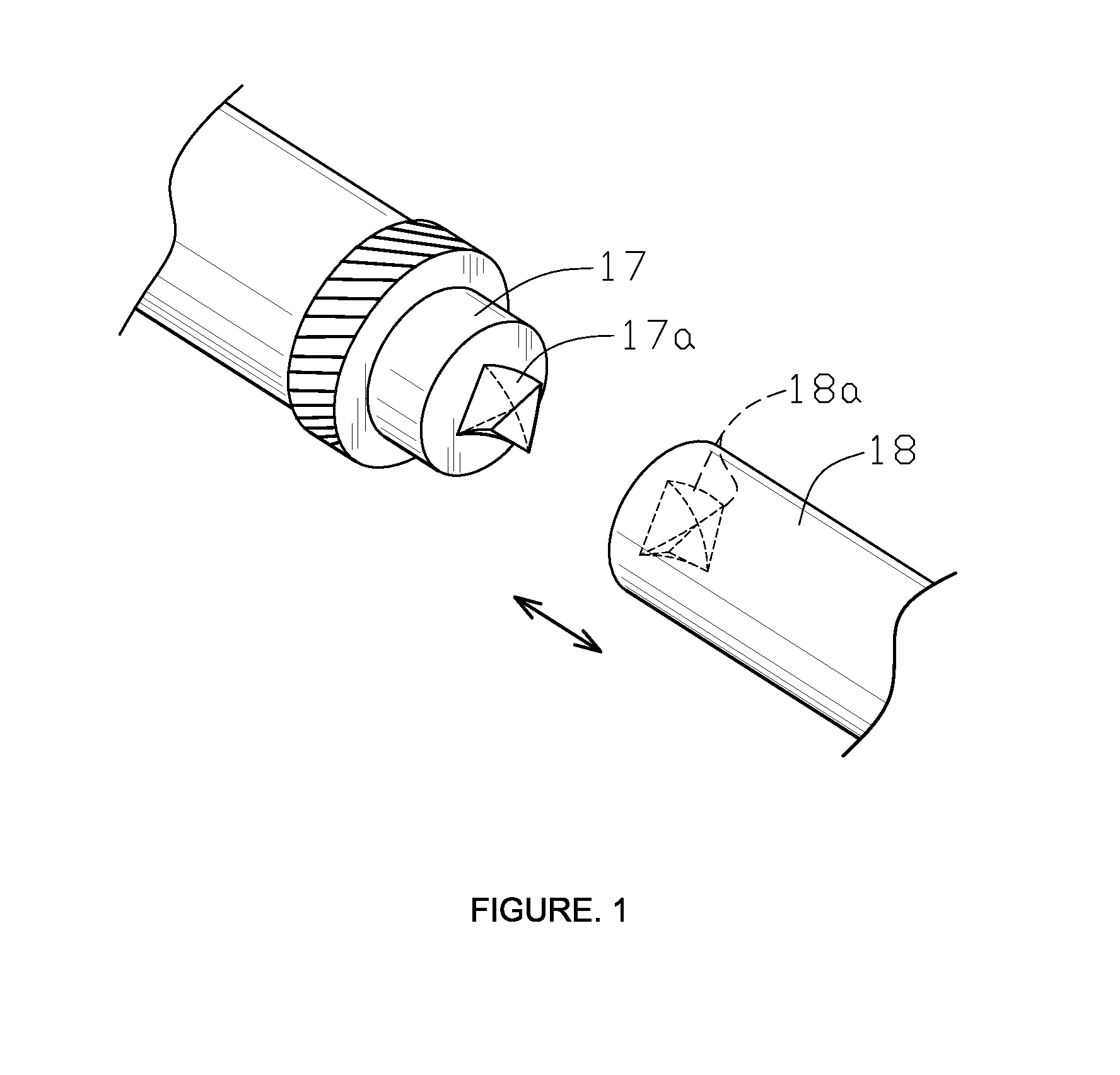
However, the process of manufacturing such a spiral triangular projection 17a is complicated, the cost of making mould is high, and the photosensitive drum driving head 17 is easy to deform or damage during long time operation, which will affect the driving accuracy and efficiency.
Additionally, according to the prior art, manufacturing spiral projection and spiral recess requires high accuracy, so there is frequently poor contact between the spiral triangular projection 17a and triangular recess 18a. It is difficult for the rotating center of the triangular recess 18a to achieve coaxial centering, which causes unnecessary sloshing between the projection and the recess during driving force transmission.
Thus, in configuration and use, conventional process cartridges still has disadvantages and defects to be further improved.
However, since years ago, no suitable device has been developed and any existing product lacks of appropriate structure for the improvement as well.
Obviously, person skilled in the art may be anxious to approach to the problems.

Method used


Image

  • Process cartridge
  • Process cartridge
  • Process cartridge

Examples


embodiment 1

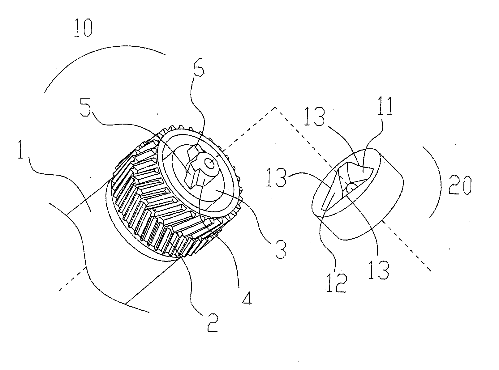
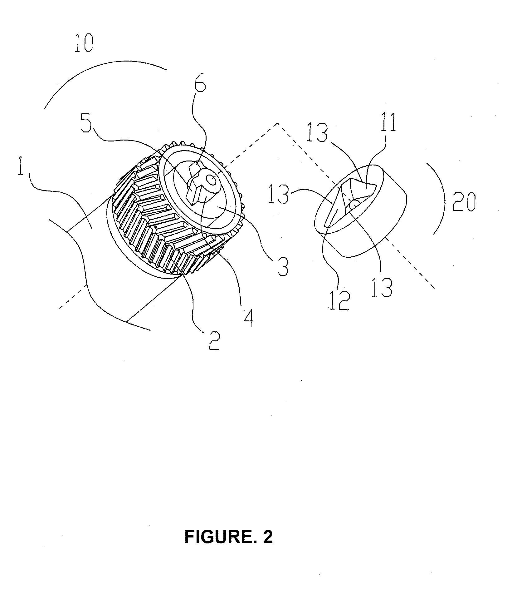
[0033]As shown in FIG. 2, a photosensitive drum driving component 10 provided in a process cartridge according to a preferred embodiment of the present invention includes a drum gear 2 provided at an end of a photosensitive drum 1 and connected to the photosensitive drum 1 for transmitting the received driving force to the photosensitive drum 1, a drum shaft 3 outwardly projected in an axis direction from an end of the drum gear 2 for rotatably supporting the photosensitive drum 1 during the operation of the process cartridge and a boss 4 outwardly projected in an axis direction from an end surface of the drum shaft 3 for receiving driving force from an image forming apparatus driving head 20. A first teeth 5 and a second teeth 6 in a radial direction of the boss 4 are provided on a side wall of the boss 4, wherein the first teeth 5 is obliquely mounted on the side wall of the boss and the second teeth 6 outwardly projected along the radial direction of the boss is vertically mounte...

embodiment 2

[0036]In the first embodiment, the photosensitive drum driving component 10 is driven by forming two points for bearing stress between both of the first teeth 5 and the second teeth 6 and the image forming apparatus driving head 20. To enhance the stability and reliability of the transmission thereof, in this embodiment as shown in FIG. 3, one more second teeth 6 outwardly projected along the radial direction of the boss 4 is additionally mounted on the boss 4 in the photosensitive drum driving component 10, compared to the first embodiment. Accordingly, three points is formed for meshing transmission while the photosensitive drum driving component 10 is engaged with the image forming apparatus driving head 20, more effective in ensuring continuous transmission.

embodiment 3

[0037]In this embodiment, as shown in FIG. 4 and FIG. 5, a section 4a perpendicular to a cross-section in the radial direction of the boss 4 is provided on the boss in the photosensitive drum driving component 10, wherein the first teeth 5 is mounted on the boss section 4a and the oblique direction of the first teeth 5 is parallel to the boss section 4a, thereby achieving advantages of better formation of a photosensitive drum driving component 10 with a first oblique teeth 5, simplified the technological process and cost saving.

[0038]The image forming apparatus driving head 20 in conjunction with the photosensitive drum driving component 10 of the present invention includes a recess 11 that may be a hole having three twisted-sections 12, each of which contains an end surface edge 13. When the process cartridge is mounted to the image forming apparatus, the boss 4 can be inserted into the twisted recess 11, wherein the first teeth 5 mounted on the boss 4 is engaged with one of the t...


PUM


Abstract

The present invention relates to a process cartridge, comprising a photosensitive drum driving component in conjunction with an image forming apparatus driving head, wherein said image forming apparatus driving head includes a twisted recess and said photosensitive drum driving component includes a drum gear provided at an end of a photosensitive drum and connected to the photosensitive drum, a drum shaft outwardly projected in an axis direction from an end of the drum gear for rotatably supporting said photosensitive drum during operation and a boss outwardly projected from an end surface of the drum shaft. A first teeth and a second teeth in a radial direction of the boss are provided on a side wall of said boss, wherein said first teeth is engaged with a twisted-section of the twisted recess in said image forming apparatus and said second teeth is engaged with an end surface edge of other twisted-sections of the twisted recess in said image forming apparatus. Thereby, the process cartridge according to this invention ensures an effectively and continuously transmitted driving force and contains a simple prepared photosensitive drum driving head, which will be less damaged even during long time operation.

Description

FIELD OF THE INVENTION[0001]The present invention relates to a process cartridge, especially a process cartridge used for an image forming apparatus.BACKGROUND TO THE INVENTION[0002]The process cartridge can be detachably mounted into a main part of an image forming apparatus, and the process cartridge, as a whole unit, comprises of an electrophotographic photosensitive member and at least one of processing means such as charging means, developing means, cleaning means, or the like. Since the process cartridge is detachably mountable relative to the main part of the device, it is easy to maintain the device. An electrophotographic image forming apparatus functions through electrophotographic image formation in the manner that an electrostatic latent image is formed by selectively exposing the electrophotographic photosensitive member uniformly charged by a charger to light from the image forming apparatus. The electrostatic latent image is developed with toner by a developing means ...

Claims


Application Information

Patent Timeline
IPC IPC(8): G03G21/18G03G15/00
CPCG03G21/186F16D3/20
Inventor ZHAO, CHUNYONG
Owner JIANGXI YIBO E TECH CO LTD
Learn More