Tool for a micro-invasive surgical instrument

Active Publication Date: 2012-10-11
KARL STORZ GMBH & CO KG
View PDF4 Cites 6 Cited by
  • Summary
  • Abstract
  • Description
  • Claims
  • Application Information

AI Technical Summary

Benefits of technology

[0047]The collar and groove, in terms of their shape and dimensions, are particularly configured in such a way that they make possible a low-friction and low-play rotation of the articulated device in relation to the connecting component. The collar in particular extends radially outward in order to engage radially from inside in the corresponding surrounding groove that is open radially toward the inside on the articulated device. The support device in this case is positioned inside the connecting component, in particular opposite the collar in the radial direction. The support device is particularly a supporting sheath in the form of a ring or tube whose outside is contiguous with an inward side of the connecting component and thus prevents a radial reshaping of the collar. Alternatively, the collar on the connecting component can engage from outside in a surrounding groov

Problems solved by technology

An instrument with a curved shaft, however, cannot always be easily rotated around its longitudinal axis inside the access way in order to modify the orientation of the tool at its distal end.
However, a few aspects both of the coupling of the too

Method used


Image

  • Tool for a micro-invasive surgical instrument
  • Tool for a micro-invasive surgical instrument
  • Tool for a micro-invasive surgical instrument

Examples


Embodiment Construction

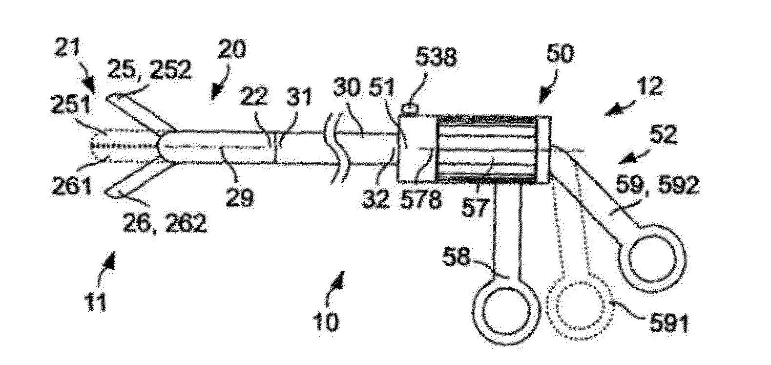
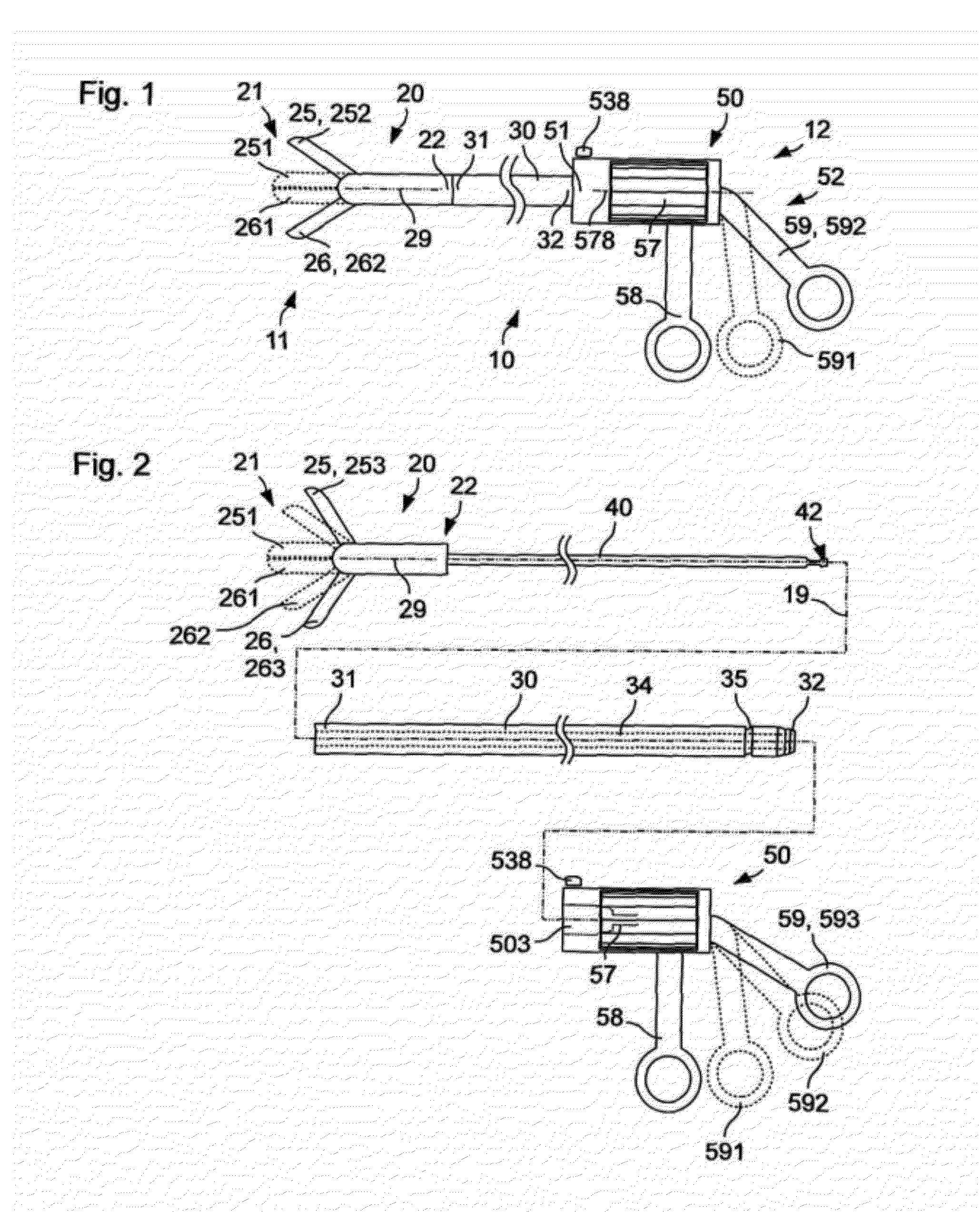
[0090]FIG. 1 shows a schematic depiction of a micro-invasive surgical instrument 10 with a distal end 11 and a proximal end 12. The micro-invasive surgical instrument 10 includes a tool 20, a shaft 30 and a handling device 50. On the distal end 21 the tool 20 comprises a first movable jaw member 25 and a second movable jaw member 26. The jaw members 25, 26 are shown in FIG. 1 in firm outline in open positions 252, 262 and in dotted lines in closed positions 251, 261. The jaw members 25, 26 can each be straight or essentially straight or can be curved in the direction perpendicular to the plane of projection of FIG. 1 and / or—contrary to the depiction in FIG. 1—in the plane of projection of FIG. 1.

[0091]The proximal end 22 of the tool 20 is detachably mechanically coupled with a distal end 31 of the shaft 30. The shaft 30 is shown strongly foreshortened in FIG. 1 and straight for the sake of simplicity. Contrary to the depiction in FIG. 1, the shaft 30 can be level or spatially curved...


PUM


Abstract

A tool, which is detachably coupleable with a shaft for a micro-invasive surgical instrument, includes an articulated device on which a jaw member or other active device is affixed, a connecting component that is rotatably connected with the articulated device and that includes a coupling device for detachable coupling with a distal end of a shaft, a transmission rod to transmit at least either a force or torque from one proximal end of a shaft detachably coupled with the tool to the jaw member or other active device, and a locking device that is coupled with the transmission rod in such a way that the locking device can be rotated with respect to the transmission rod but not slid axially, so that the locking device is mounted in the connecting component in such a way that it can be axially slid but not rotated in relation to the connecting component.

Description

CROSS-REFERENCE TO RELATED APPLICATIONS[0001]The present application claims priority of German patent application No. 10 2011 007 122.9 filed on Apr. 11, 2011, the content of which is incorporated herein by reference.FIELD OF THE INVENTION[0002]The present invention relates to a tool for a micro-invasive surgical instrument, a micro-invasive surgical instrument and thus, in particular, characteristics for mechanical coupling of the tool with a distal end of a shaft.BACKGROUND OF THE INVENTION[0003]Many micro-invasive surgical instruments include a long, thin shaft, a tool on the distal end of the shaft and a handling device on the proximal end of the shaft. The tool includes, for example, a grasping, dissecting, biopsy or other forceps, a scissors or a needle holder with at least two straight or curved clamps, cutting edges or other jaw members of which at least one is movable. Alternatively, the tool includes another active device, for example a manipulator with a finger or a finge...

Claims


Application Information

Patent Timeline
IPC IPC(8): A61B17/00
CPCA61B17/29A61B2017/0046A61B2017/00477A61B2017/294A61B2017/2931A61B2017/2945A61B2017/2939A61B2017/2929
Inventor STEFAN, JOCHENKAERCHER, DANIELBACHER, UWE
Owner KARL STORZ GMBH & CO KG
Why Eureka
Try Eureka