
Commode ventilator

a ventilator and commode technology, applied in water installations, lavatory sanitory, construction, etc., can solve the problems of releasing objectionable odors into the atmosphere, affecting the efficiency of air evacuation systems, so as to maximize the effectiveness of air evacuation systems

Inactive Publication Date: 2012-10-18
KING RICHARD
View PDF11 Cites 1 Cited by
  • Summary
  • Abstract
  • Description
  • Claims
  • Application Information

AI Technical Summary

Benefits of technology

[0005]The present invention provides apparatus which collects and disposes of air from the vicinity of a commode. The apparatus draws from the immediate vicinity of the commode and conducts collected air to a room exhaust fan. The apparatus comprises an inlet mountable to the commode, a conduit extending to the inlet grille of the exhaust fan, and an enclosure which constrains the exhaust fan to draw exclusively or almost exclusively from the conduit, thereby maximizing effectiveness of the air evacuation system.
[0006]The conduit is adapted to mount to room surfaces, such as the partition and ceiling, thereby being minimally intrusive with respect to the room, and for secure anchorage on the commode. The entire apparatus is uncomplicated, lightweight, inexpensive, and easily installable. Reliance upon integral power providing and utilizing apparatus is eliminated.
[0009]Another object of the invention is that the air evacuation system be uncomplicated, inexpensive, and easily installed.
[0010]It is an object of the invention to provide improved elements and arrangements thereof by apparatus for the purposes described which is inexpensive, dependable, and fully effective in accomplishing its intended purposes.

Problems solved by technology

Use of commodes typically entails release of objectionable odors into the atmosphere.
This causes fouled air to blend with the remaining air, so that the atmosphere of nearly the entire room becomes fouled.
While this approach seems intuitively superior to depending on a wall or ceiling mounted exhaust fan, most executions of the approach cause the apparatus to become unduly cumbersome and impractical.
Not only does this cause the air collection device to become heavier and more expensive, but it further introduces the necessity of incorporating a power supply such as a battery, or introduces necessity of connecting to a wall mounted electrical receptacle.
There remains a need for an air evacuation system which draws from the immediate vicinity of the commode, and yet which is uncomplicated and practical.

Method used


Image

  • Commode ventilator
  • Commode ventilator
  • Commode ventilator

Examples


Embodiment Construction

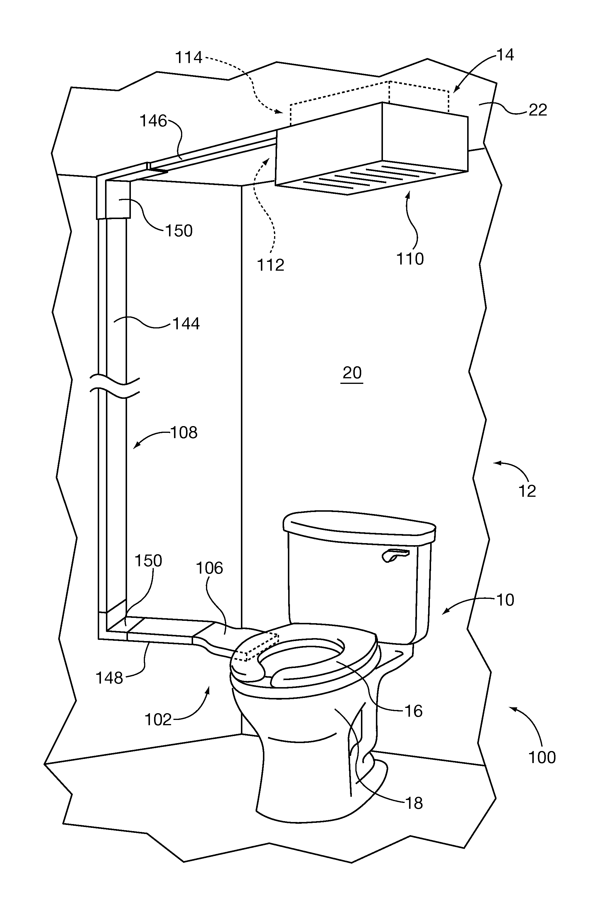
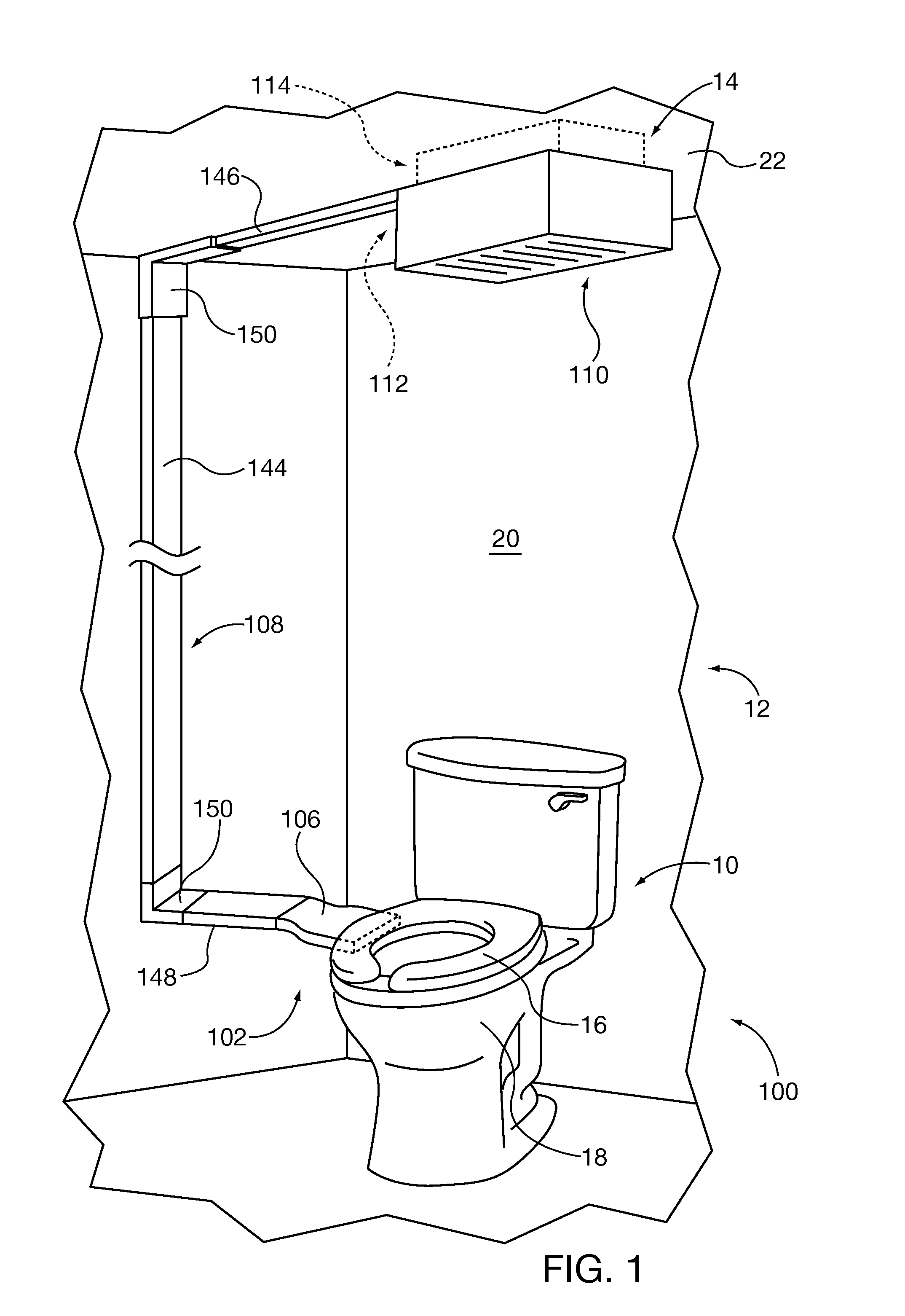
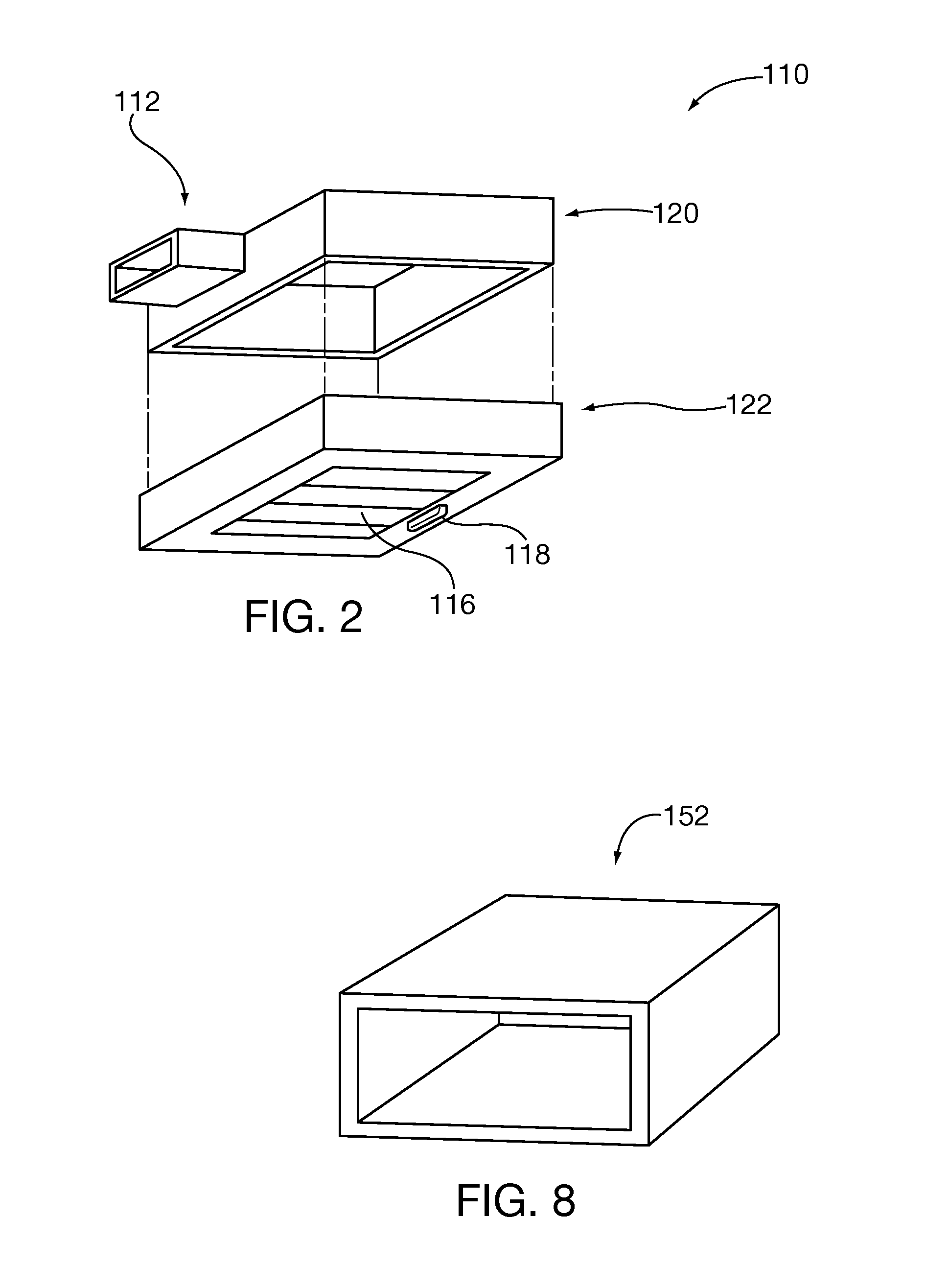
[0026]Referring first to FIG. 1, according to at least one aspect of the invention, there is shown apparatus 100 for collecting and discharging odoriferous air from the vicinity of a commode 10 located in a room 12 provided with an exhaust fan 14 (not visible in its entirety) having an inlet to receive air from the room 12. The apparatus 100 may comprise an intake member 102 having an intake end 154 and a discharge end 106 of configuration different from that of the intake end 154. Air inducted from the intake member 102 flows into a conduit 108 which is insertably compatible with the discharge end 106 of the intake member 102. Air flows through the conduit 108 to an adapter housing 110 which is disposed to connect the elongated conduit 108 to the inlet of the exhaust fan 14. The adapter housing 110 also substantially seals against draw of air by the exhaust fan 14 from the atmosphere outside the adapter housing 110. It will be understood that air flow through the apparatus 100 is e...


PUM


Abstract

Apparatus for collecting and disposing of air from the vicinity of a commode, utilizing a room exhaust fan. The apparatus may comprise an air intake member mountable to the commode, a conduit extending to the inlet grille of the exhaust fan, and an adapter housing which fits over the intake of the fan and constrains the exhaust fan to draw exclusively or almost exclusively from the conduit. The conduit may comprise flat sided plural sections, with connecting sleeves and right angled elbow connectors. The adapter housing may bear closable louvers. The air intake member may be mounted to the commode using an adhesive bearing anchor, occupying the space between the bowl and the toilet seat. The apparatus may include clips for securing the conduit to a wall surface. The air intake member may be rigid or flaccid.

Description

FIELD OF THE INVENTION[0001]The present invention relates to evacuation of odoriferous near commodes by drawing air from the environment of the commode and discharging the same.BACKGROUND OF THE INVENTION[0002]Use of commodes typically entails release of objectionable odors into the atmosphere. Current practice is to provide bathrooms with exhaust fans for discharging odoriferous air. However, exhaust fans are typically located high in the room, at the ceiling in most cases. This causes fouled air to blend with the remaining air, so that the atmosphere of nearly the entire room becomes fouled. While an exhaust fan may eventually evacuate the fouled air, there is still considerable opportunity for the odor firstly, to permeate the entire room, and secondly, to spread beyond the bathroom.[0003]The prior art has suggested diverse devices to collect air from the immediate vicinity of a commode, and to discharge this air. While this approach seems intuitively superior to depending on a w...

Claims


Application Information

Patent Timeline
IPC IPC(8): E03D9/04
CPCE03D9/05
Inventor KING, RICHARD
Owner KING RICHARD
Learn More