
Flow ultracapacitor

a technology of ultracapacitors and ultracapacitors, which is applied in the direction of electrolytic capacitors, liquid electrolytic capacitors, transportation and packaging, etc., can solve the problems of not being economically feasible, not counting the cost of modules and system integration, and existing commercial ultracapacitors costing $14,800/kwh

Inactive Publication Date: 2012-10-18
BASF AG
View PDF8 Cites 67 Cited by
  • Summary
  • Abstract
  • Description
  • Claims
  • Application Information

AI Technical Summary

Benefits of technology

[0021]These and other aspects of the invention will be apparent upon reference to the attached drawings and following detailed description. To this end, various refer

Problems solved by technology

Ultracapacitors have advantages in electrical grid applications because of their extraordinary cycle life and longevity, but using existing commercial ultracapacitors would cost $14,800 / kWh (not counting module and system integration cost); which is not economically feasible.
Unfortunately these systems cost in the $300-500 / kWh range.
Generally, flow batteries or molten metal batteries are still too expensive and have substantial operating drawbacks such as poor cycle life, low efficiency, and high operating temperature.
Ultracapacitors solve problems associated with batteries but are far too expensive for bulk storage grid applications.

Method used


Image

  • Flow ultracapacitor
  • Flow ultracapacitor
  • Flow ultracapacitor

Examples


example 2

Flow Device

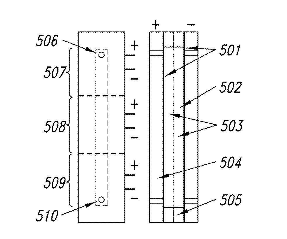
[0134]A flow device was prepared as illustrated in FIG. 5. The device comprised a carbon electrode material, electrolyte (TEA TFB), current collectors 501, an inert porous separator 502, charge channels 503, an outer structure 504 and gaskets 505. Studies conducted with this device indicate that the electrode material becomes charged as it flows through the device. During operation of the device, the electrode suspension moved from an inlet 506 in zone 1507 through zone 2508 to an outlet 510 in zone 3509. Measurements were taken in each zone as the electrode suspension flowed through the electrochemical cell. The voltage was held at 2V with a relatively steady current and electrode flow was initiated at ˜940 seconds. FIG. 6 shows that the current requirement of Zone 1 increased immediately with zones 2 and 3 lagging in current accepting capability until fresh—uncharged—electrode material arrived in the respective zones. The charged electrode suspension was captured into ...


PUM


Abstract

The present application is generally directed towards electrochemical energy storage devices. The devices comprise electrode material suspended in an appropriate electrolyte. Such devices are capable of achieving economical $ / kWh(cycle) values and will enable much higher power and cycle life than currently used devices.

Description

CROSS-REFERENCE TO RELATED APPLICATION[0001]The present application claims the benefit under 35 U.S.C. §119(e) of U.S. Provisional Patent Application No. 61 / 476,136 filed on Apr. 15, 2011; which application is incorporated herein by reference in its entirety.BACKGROUND[0002]1. Technical Field[0003]The present invention generally relates to electrochemical energy storage devices and, in particular, to flow ultracapacitors.[0004]2. Description of the Related Art[0005]Ultracapacitors have advantages in electrical grid applications because of their extraordinary cycle life and longevity, but using existing commercial ultracapacitors would cost $14,800 / kWh (not counting module and system integration cost); which is not economically feasible. There are major efforts underway to reduce cost, but ultracapacitors will continue to be designed for high volumetric energy and power density making them most useful for portable applications.[0006]Flow batteries are designed for the grid and have l...

Claims


Application Information

Patent Timeline
IPC IPC(8): H01G9/042H01G9/145H02J7/00H01G9/155H01G9/15B82Y30/00B82Y99/00
CPCH01G9/042H01G9/145Y02E60/13H01G11/30H01G11/58H01G9/155H01G11/26H01G11/24H01G11/10H01G11/14
Inventor FEAVER, AARONVARJIAN, RICHARDGOODWIN, CHAD
Owner BASF AG
Learn More