Interaction chamber with flow inlet optimization

a technology of flow inlet optimization and interaction chamber, which is applied in the directions of mixing, transportation and packaging, chemistry apparatus and processes, etc., can solve the problem of high energy dissipation

Active Publication Date: 2012-10-18
MICROFLUIDICS INT
View PDF12 Cites 21 Cited by
  • Summary
  • Abstract
  • Description
  • Claims
  • Application Information

AI Technical Summary

Problems solved by technology

The fluid paths at the discharge end of each of the mixing chamber elements mix with one another under high pressure, resulting in the high energy dissipation.

Method used


Image

  • Interaction chamber with flow inlet optimization
  • Interaction chamber with flow inlet optimization
  • Interaction chamber with flow inlet optimization

Examples


Embodiment Construction

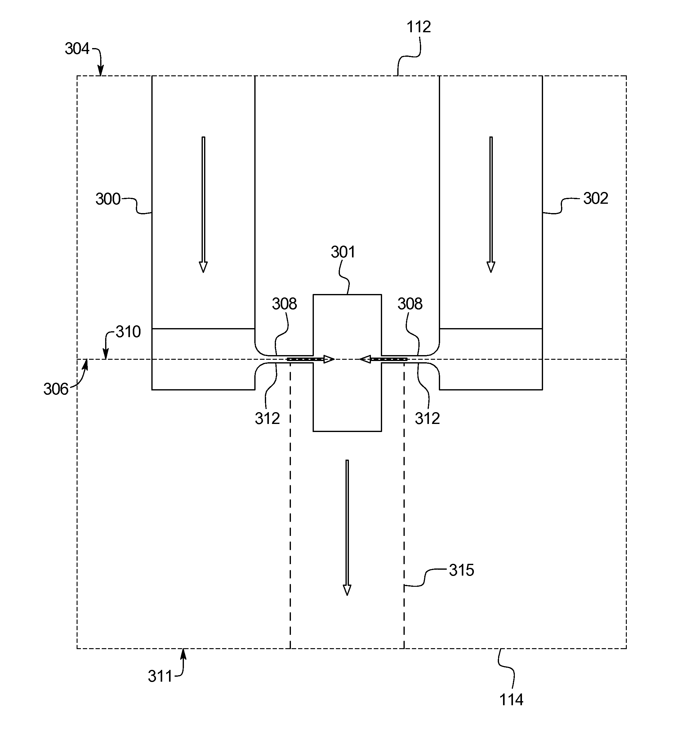
[0018]The present disclosure is generally directed to an interaction chamber that includes mixing chamber elements with curved flow inlets to reduce flow resistance and increase discharge fluid flow rate. The curved flow inlets result in the superior mixture of fluid using less energy than current mixing devices. By decreasing the flow resistance in the curved inlet of the mixing chamber elements, the fluid flow rate entering the mixing chamber elements can be increased as well, resulting in significant energy savings without sacrificing quality and consistency of the mixing.

[0019]The curved inlets are part of an interaction chamber, as described in U.S. patent application Ser. No. 12 / 986,477, which is incorporated herein by reference. Also incorporated herein by reference is U.S. Patent Application identified by Attorney Docket No. 0813715-10201 directed to a mixing chamber with an impinging micro fluid flow path configuration. It should be appreciated, however, that the curved inl...


PUM

PropertyMeasurementUnit
volumeaaaaaaaaaa
volumeaaaaaaaaaa
temperatureaaaaaaaaaa

Abstract

A mixing assembly includes an inlet, an outlet and a mixing chamber, the inlet is fluidly connected to the outlet through a plurality of micro fluid flow paths in a direction perpendicular from the inlet. The micro fluid flow paths fluidly connect to the perpendicular inlet via a curved transition portion. The curved transition portion provides a more efficient flow path for the fluid to travel from the inlet to the micro fluid flow paths to the mixing chamber. By transitioning the direction change, flow resistance is decreased, and the fluid flow rate and shear rate is increased. Increased fluid flow rate and shear rate helps to increase consistency and quality of mixing, and to reduce particle size of the fluid in the mixing chamber.

Description

CROSS-REFERENCE TO RELATED APPLICATIONS[0001]This application expressly incorporates by reference, and makes a part hereof, U.S. patent application Ser. No. 12 / 986,477 and the U.S. Patent Application identified by Attorney Docket Number 0813715.10201, entitled: “Compact Interaction Chamber with Multiple Cross Micro Impinging Jets”, filed on behalf of the same inventors concurrently with the present application.[0002]A portion of the disclosure of this patent document contains material which is subject to copyright protection. The copyright owner has no objection to the photocopy reproduction of the patent document or the patent disclosure in exactly the form it appears in the Patent and Trademark Office patent file or records, but otherwise reserves all copyright rights whatsoever.BACKGROUND OF THE INVENTION[0003]For certain pharmaceutical applications, manufacturers need to process and mix expensive liquid drugs for testing and production using the lowest possible volume of fluid t...

Claims


Application Information

Patent Timeline
Patent Type & Authority Applications(United States)
IPC IPC(8): B01F15/02
CPCB01F5/0256B01F2215/0032B01F13/0059B01F25/23B01F33/30B01F2101/22B01F23/451
Inventor XIONG, RENQIANGBERNARD, JOHN MICHAEL
Owner MICROFLUIDICS INT
Why Eureka
Try Eureka