
Device and method for measuring mechanical path lengths by means of pneumatic pressure, in particular for sliding carbon contacts

a technology of mechanical path length and pneumatic pressure, which is applied in the direction of rotary current collectors, structural/machine measurement, instruments, etc., can solve the problems of destroying sliding contact tracks, detecting progressive wear of brushes, and interrupting contact, so as to achieve high electrical insulation

Inactive Publication Date: 2006-03-14
SCHLEIFRING & APPBAU
View PDF29 Cites 22 Cited by
  • Summary
  • Abstract
  • Description
  • Claims
  • Application Information

AI Technical Summary

Benefits of technology

"The invention provides a device and method for non-contacting measurement of the length of sliding contact brushes used in sliding contact track systems or collector systems. The device includes a pneumatic pressure source, a pressurized air line, a pressure sensor, and an evaluation circuit for measuring changes in air pressure. The method involves feeding pressurized air into the brush and measuring the pressure drop to determine the length of the brush. The device and method provide a simple and cost-effective solution for measuring the length of sliding contact brushes."

Problems solved by technology

Sliding contacts and in particular mechanical slip-rings in which use is made of carbon brushes or brushes of other materials frequently give rise to the problem of detecting progressive wear of the brushes.
Worn brushes may lead to interruptions of contact or even to a destruction of sliding contact tracks.
For example, if the brushes of slip-rings are worn down to the extent that reliable contact can no longer be ensured, sparking may occur which in turn leads to an increased wear of brushes and sliding contact tracks.
Thus, an only brief operation with worn brushes may lead to greater wear of a slide track than occurs during the remaining operating life of the brush.
These have the advantage of providing good insulation, but also the disadvantage of having high complexity, thus being costly.
However, they are not particularly robust, because requirements of size permit the use of only relatively small and therefore fragile contact members.
These contacts are liable to be mechanically damaged, particularly during a replacement of carbon brushes, then they will no longer indicate the presence of a worn brush.
Furthermore, these contacts may be contaminated by carbon dust or other abraded material with the result of their electrical and mechanical operation being impaired.
Further known solutions of the problem concern relatively complicated mechanical devices for actuating a switch contact in the event of extensive contact wear.
However, because of their high complexity these solutions involve considerable outlay and structural size.
Therefore they are preferably suitable for large electrical machinery, but not for modern slip-ring systems which usually must be incorporated into an extremely limited assembly space.
With progressive wear on the brush, the insulation of the conductor is worn away and the conductor contacts the slide track.
These systems are characterized by being of extremely simple mechanical design, however, they do not permit of any isolation of electrical potentials.
All of the mentioned systems have the disadvantage of involving much outlay and therefore being expensive to fabricate.
Furthermore, they involve the use of a number of complicated electrical and optical components which are prone to failure.

Method used


Image

  • Device and method for measuring mechanical path lengths by means of pneumatic pressure, in particular for sliding carbon contacts
  • Device and method for measuring mechanical path lengths by means of pneumatic pressure, in particular for sliding carbon contacts
  • Device and method for measuring mechanical path lengths by means of pneumatic pressure, in particular for sliding carbon contacts

Examples


Embodiment Construction

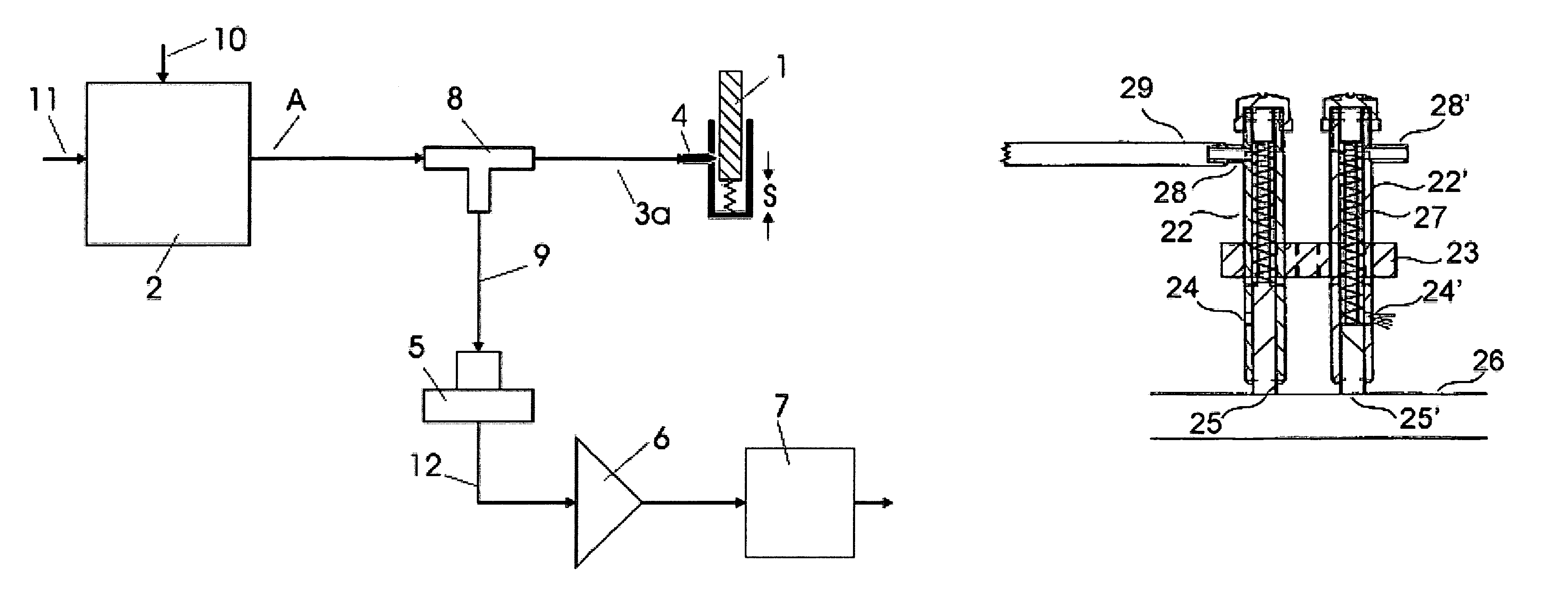
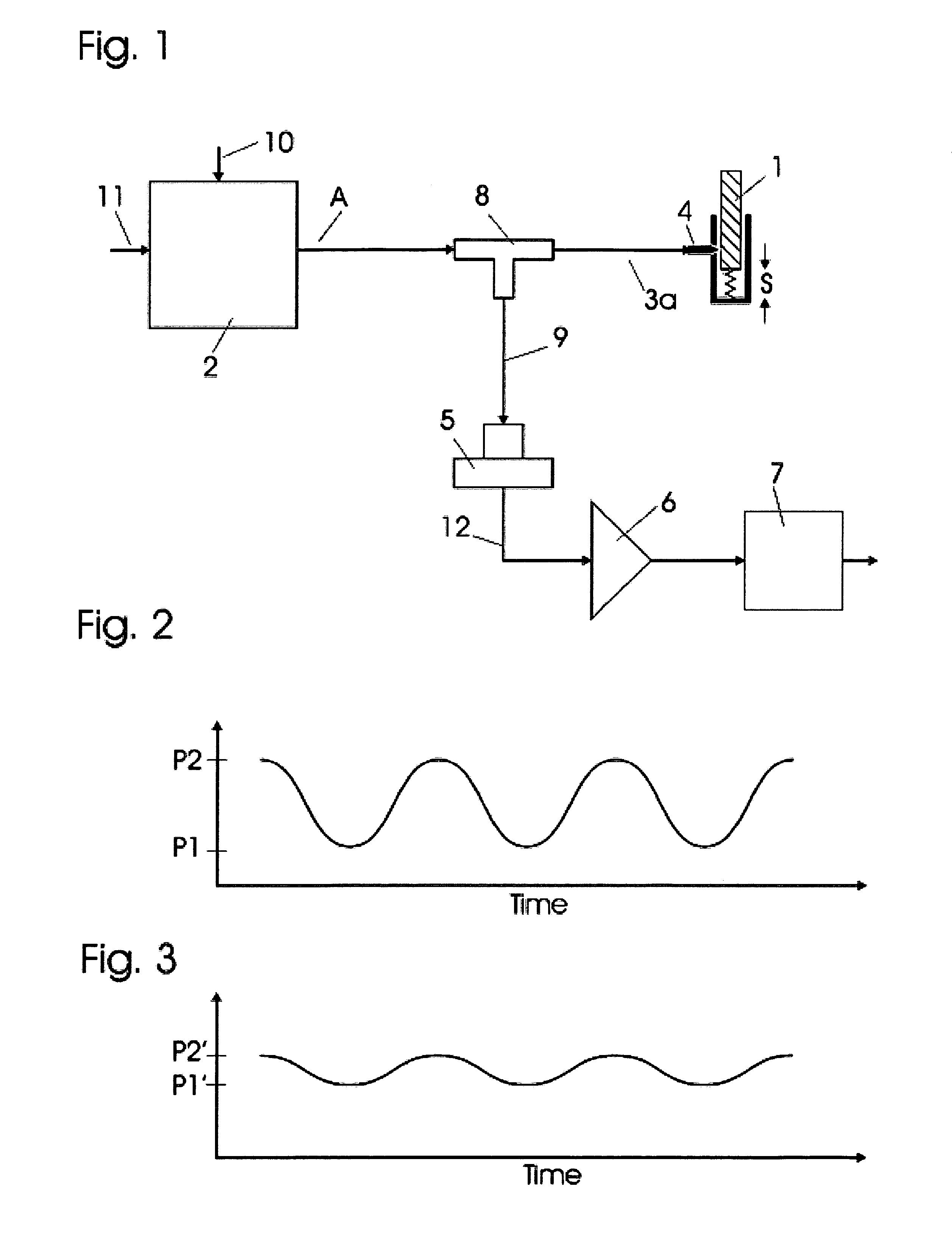
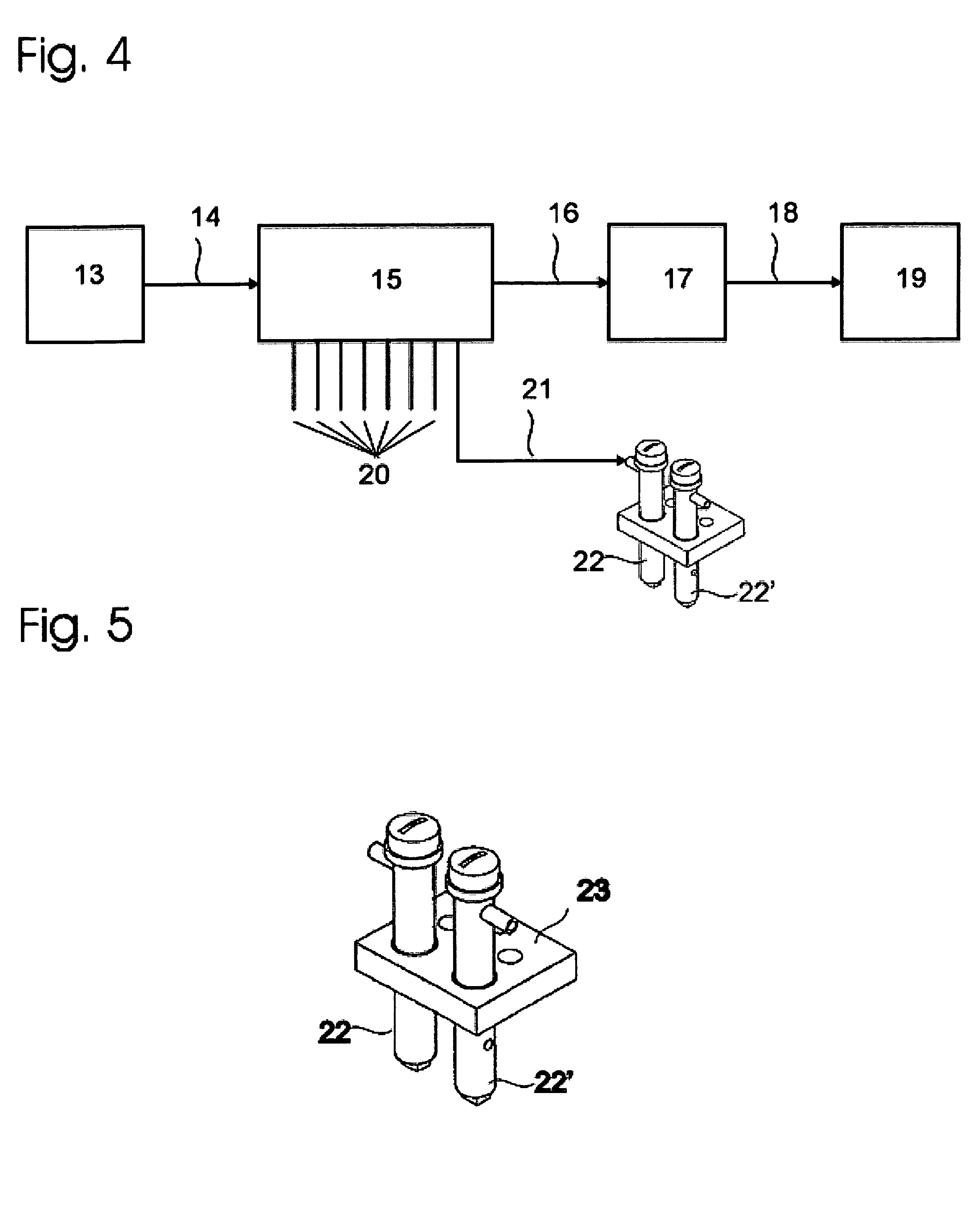
[0040]In the device according to the first aspect of the invention as shown in FIG. 1, a non-contacting measurement of a length or a path is performed by means of a pulsating air current. A pump 2, preferably driven by an electric motor connected to an electrical supply line 10 and operated at 24 V d.c., or by any other power source, takes in air through an air intake 11 and generates a pulsating air pressure. Of course, any other suitable gas such as nitrogen or an insulating inert gas may be used. Pumps for producing the air pressure changes may be piston pumps, diaphragm pumps particularly having a piezo diaphragm, or other pumps of known type. It is essential to the invention that the pump produce a defined fluctuating preferably an oscillating air pressure at its outlet to a pressurized air line 3. FIG. 2 shows fluctuations of pressure between values P1 and P2 at a pump outlet in the line 3. Optionally, the pressure value may fluctuate in a positive direction, for example from ...


PUM


Abstract

In a device and a method for measuring path lengths, particularly of brushes in sliding contacts, an air stream having a regularly fluctuating pressure is provided by a pump and conducted via an air supply line and a nozzle to an object to be measured. The object is disposed so that its length or position affects the flow resistance of passing air. A consequent pressure drop in the supply line is determined with a pressure sensor, and an evaluation unit computes, in particular from the difference between maximum and minimum air pressure, a length of the object as a function of the pressure difference. In another embodiment of the invention, pressurized air is supplied from a pump to an object to be measured, and a sensor is disposed to detect a pressure change when the object has attained a predetermined length.

Description

FIELD OF THE INVENTION[0001]The present invention relates to a device and a method for non-contacting measurement of mechanical path lengths by pneumatic means, in particular for determining the wear of electrical sliding-contact and slip-ring brushes.DESCRIPTION OF THE PRIOR ART[0002]Sliding contacts and in particular mechanical slip-rings in which use is made of carbon brushes or brushes of other materials frequently give rise to the problem of detecting progressive wear of the brushes. Worn brushes may lead to interruptions of contact or even to a destruction of sliding contact tracks. For example, if the brushes of slip-rings are worn down to the extent that reliable contact can no longer be ensured, sparking may occur which in turn leads to an increased wear of brushes and sliding contact tracks. Thus, an only brief operation with worn brushes may lead to greater wear of a slide track than occurs during the remaining operating life of the brush. This case may be less critical f...

Claims


Application Information

Patent Timeline
Patent Type & Authority Patents(United States)
IPC IPC(8): G01B13/04H01R39/58
CPCH01R39/58
Inventor DINGFELDER, HERBERTHUTTERER, RAINER
Owner SCHLEIFRING & APPBAU
Learn More