System and method for a microfluidic calorimeter

a microfluidic calorimeter and microfluidic technology, applied in the field of microfluidic calorimeters, can solve the problems of low sensitivity of reaction, compound with poor solubility frequently generating hits on high throughput screens, and achieve the effect of reducing noise and error in data

Active Publication Date: 2012-10-18
NORTHEASTERN UNIV +1
View PDF1 Cites 13 Cited by
  • Summary
  • Abstract
  • Description
  • Claims
  • Application Information

AI Technical Summary

Benefits of technology

[0011]There is therefore a need in the pharmaceutical industry for a system and method for microfluidic calorimetry. Extraordinary optical transmission, a physical phenomenon, related to surface plasmon resonance, can be harnessed to produce an apparatus for determining temperature change of a chemical reaction occurring in microfluidic laminar flow. In addition to solving the aforementioned needs for such a calorimeter, the microfluidic calorimeter disclosed herein uses a stationary laminar flow with numerous benefits over traditional calorimetry methods. First, the exact volume of the reagents need not be known. Second, flowing the reagents and observing the reaction along the channel allows the reaction to be observed as it progresses, since the reagents continue to diffuse and react as they flow. Third, since the reaction and diffusion regions are stationary in space, which implies that the heat released at a location along the channel should remain constant for the duration of the test, the collected data can be integrated over time to reduce noise and error in the data.

Problems solved by technology

The limitations of the current generation of calorimeters include:Inadequate sensitivity for reactions with a low change in enthalpyLarge amount of protein required (0.5 mg to 5 mg)Low experimental throughput because of both long experiment run times (60 to 90 minutes) and the need to sequentially run controls to assess the significance of the confounding effects.
Furthermore, compounds with poor solubility frequently generate hits in high throughput screens.
Unfortunately, the concentrations of these compounds required to meet the mass requirement for reagents (protein and its ligand) are often above the solubility limit.
As a result, calorimetry studies on the interactions of these compounds with their targets cannot be done.
Paradoxically, additional synthetic / medicinal chemistry is required before calorimetry can be used, but this chemistry work cannot be justified without the calorimetry data.
The outcome of this is that potentially promising compounds are not pursued.

Method used


Image

  • System and method for a microfluidic calorimeter
  • System and method for a microfluidic calorimeter
  • System and method for a microfluidic calorimeter

Examples


Embodiment Construction

[0041]To provide an overall understanding of the invention, certain illustrative embodiments will now be described, including systems and methods for microfluidic calorimetry. However, it will be understood by one of ordinary skill in the art that the systems and methods described herein may be adapted and modified as is appropriate for the application being addressed and that the systems and methods described herein may be employed in other suitable applications, and that such other additions and modifications will not depart from the scope thereof.

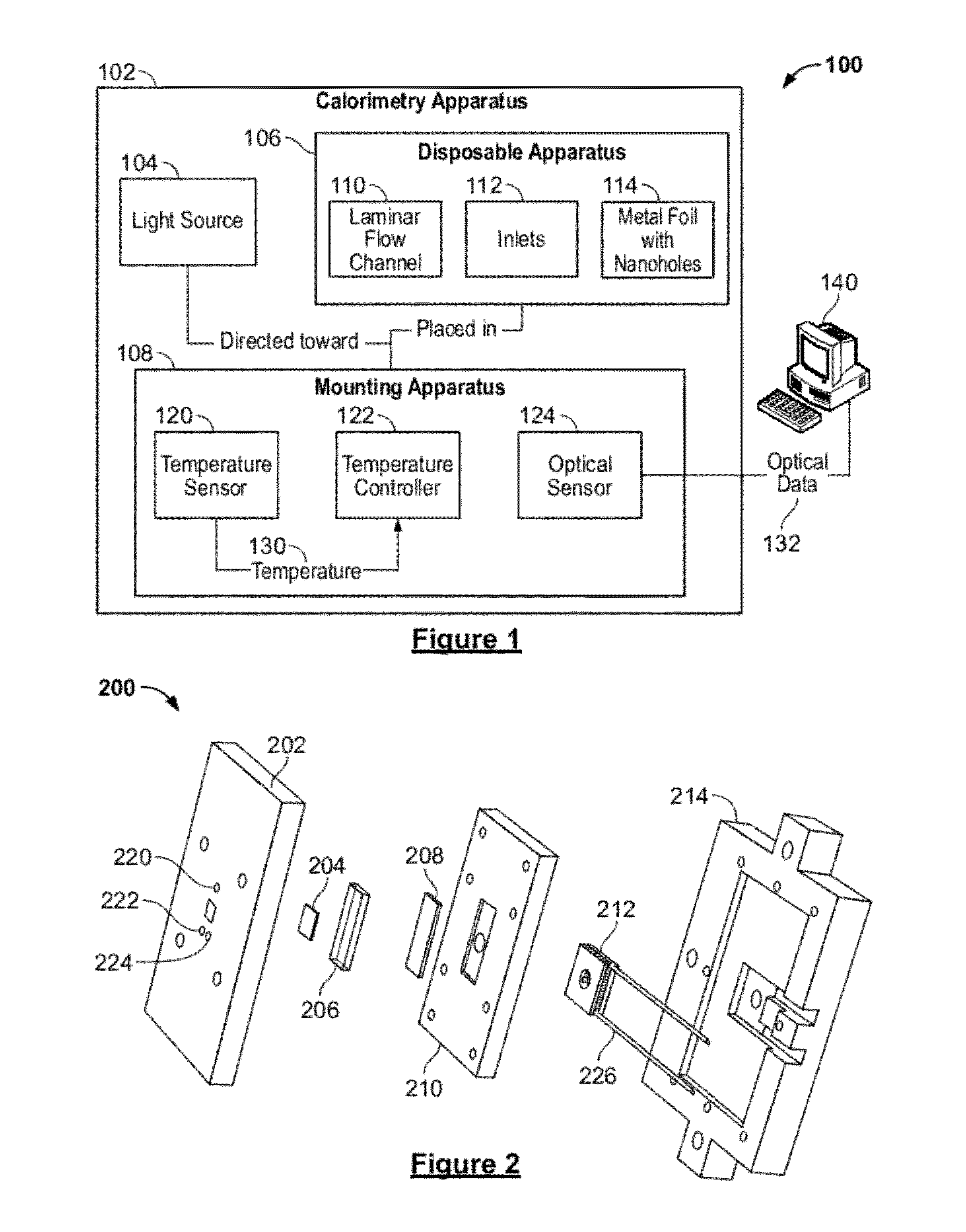
[0042]FIG. 1 is a block diagram of a system for microfluidic calorimetry 100, according to an illustrative embodiment of the invention. The system 100 is used to detect temperature change and other calorimetry measurements from a micro-scale chemical reaction. A user runs an experiment in the microfluidic calorimeter by flowing two reagents into and through a laminar flow channel, causing the reagents to react at their diffusion interfac...


PUM

PropertyMeasurementUnit
currentaaaaaaaaaa
diameteraaaaaaaaaa
diameteraaaaaaaaaa

Abstract

Systems and methods are disclosed herein for a microfluidic calorimeter apparatus. A microfluidic calorimeter system includes a calorimetry apparatus and a processor in connection with the apparatus. The apparatus includes a microfluidic laminar flow channel connected to two inlets for flowing fluid into the laminar flow channel. Below the laminar flow channel is a plurality of microscale temperature sensors at known positions in the channel. The processor is in connection with the discrete temperature sensors and determines a calorimetry measurement based on local temperatures derived from data output by the microscale temperature sensors and the respective positions of the sensors in the channel.

Description

CROSS-REFERENCE TO RELATED APPLICATIONS[0001]This application claims the benefit of U.S. Provisional Application No. 61 / 433,167, filed Jan. 14, 2011, which is incorporated by reference herein in its entirety.FUNDING[0002]Work described herein was funded, in whole or in part, by Grant No. R21CA131884, awarded by the National Cancer Institute and the National Institute of Health. The United States Government has certain rights in the invention.FIELD OF THE INVENTION[0003]In general, the invention relates to a microfluidic calorimetry system and a method for using a microfluidic calorimeter. More specifically, the invention relates to a system and method for providing two reagents in microfluidic laminar flow, detecting optical signals transmitted through arrays of nanoholes in a metal film, and processing the optical data to obtain a calorimetry measurement.BACKGROUND OF THE INVENTION[0004]calorimetry is a valuable tool in pharmaceutical research and development, providing information...

Claims


Application Information

Patent Timeline
Patent Type & Authority Applications(United States)
IPC IPC(8): G01N25/48G01N25/00
CPCB82Y15/00G01K17/006G01N21/05G01N21/554G01N25/4873G01N2021/0346G01N25/482
Inventor FIERING, JASON O.LARSON, DALEKOWALSKI, GREGORYSEN, MEHMET
Owner NORTHEASTERN UNIV
Why Eureka
Try Eureka