Storage subsystem, data migration method and computer system
a data migration and storage subsystem technology, applied in computing, instruments, electric digital data processing, etc., can solve problems such as unintentional unbalanced resource utilization ratios in storage subsystems
- Summary
- Abstract
- Description
- Claims
- Application Information
AI Technical Summary
Benefits of technology
Problems solved by technology
Method used
Image
Examples
first embodiment
[0040]A first embodiment of this invention is described with reference to FIGS. 1 to 15.
[0041]A main feature of the first embodiment is that storage subsystems permitted to access a port of a source storage subsystem from which a volume is migrated are limited, with the type of migration managed on a source volume basis, so that a destination storage subsystem recognizing a volume can determine that the destination storage subsystem is permitted to acquire the volume and can execute processing appropriate for the volume.
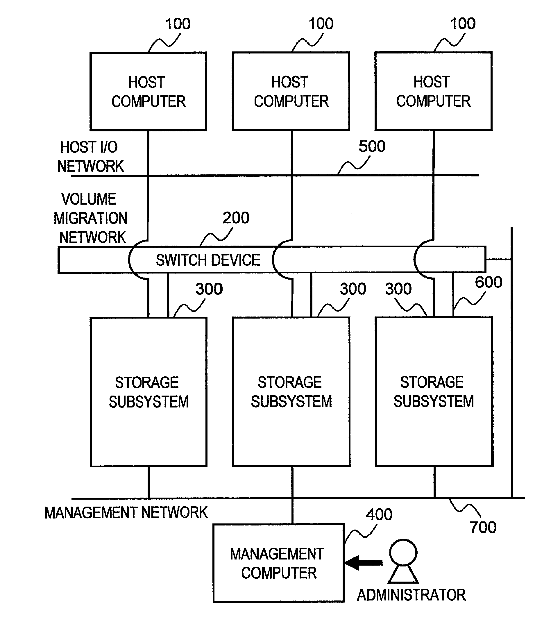
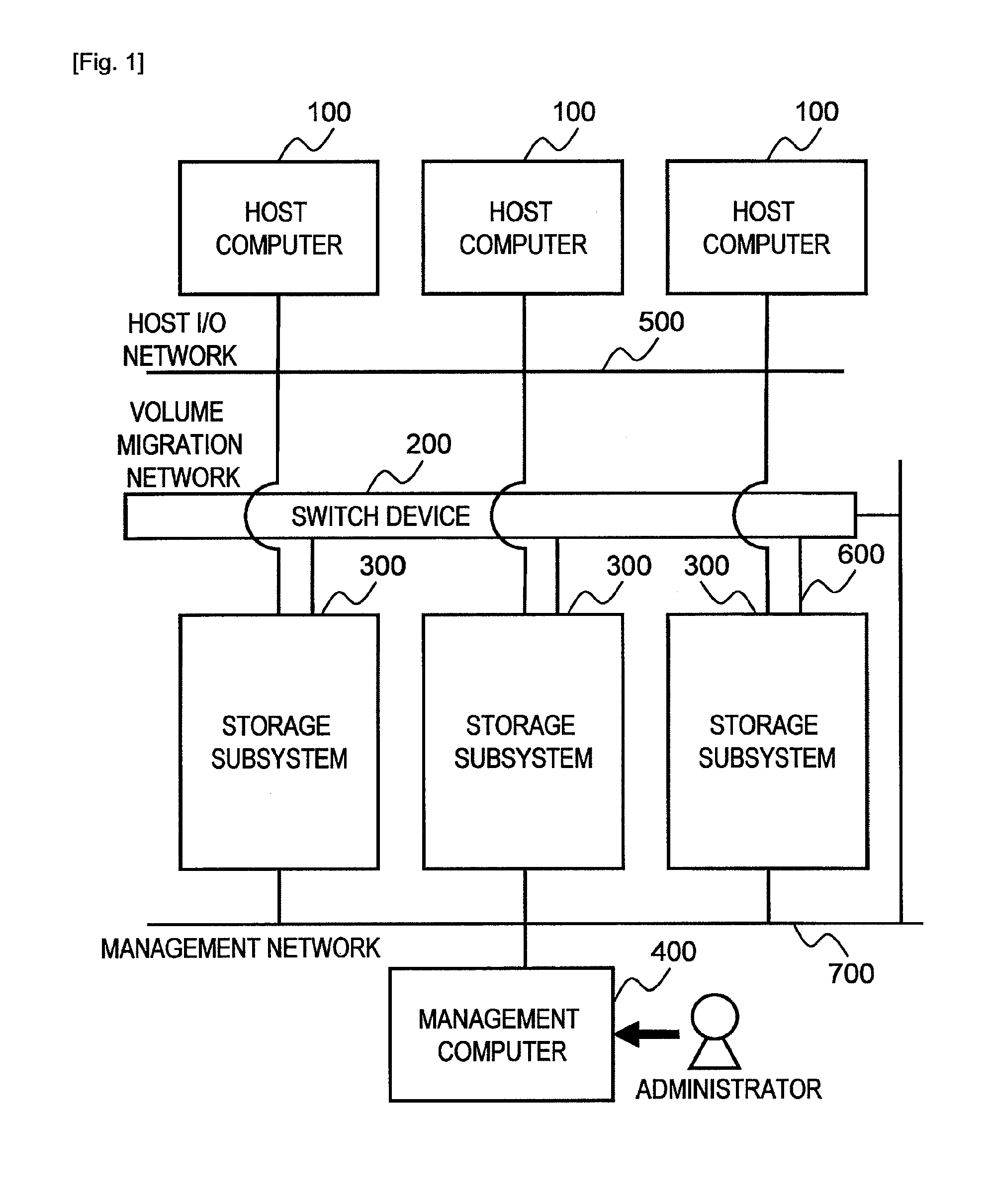
[0042]FIG. 1 is a block diagram illustrating the configuration of a computer system according to the first embodiment of this invention.
[0043]The computer system of the first embodiment includes a plurality of host computers 100, a plurality of storage subsystems 300, and a management computer 400.
[0044]The host computers 100 are coupled to the storage subsystems 300 via a host I / O network 500 to issue a data write request and a data read request to the storage subsy...
second embodiment
[0145]In a second embodiment, the switch device sets zoning that allows a source storage subsystem and destination storage subsystem specified by an administrator to communicate with each other. Specifically, the second embodiment uses the switch device to limit storage subsystems permitted to access a source storage subsystem, with the type of migration managed in advance on a source volume basis. At the time a destination storage subsystem recognizes a volume, whether or not the destination storage subsystem is permitted to acquire the volume is determined, which ensures that processing executed for a volume is appropriate for the volume.
[0146]A computer system of the second embodiment has the same configuration as the system configuration (illustrated in FIG. 1) described in the first embodiment. The configurations of the host computers 100, the switch device 200, and the storage subsystems 300 in the second embodiment are the same as those in the first embodiment. The management...
third embodiment
[0185]A third embodiment is described next. While the first embodiment described above uses settings that are set to a port of a source storage subsystem to control the access of other storage subsystems to a source volume, the third embodiment uses settings that are set to a port of a destination storage subsystem to control the access of other storage subsystems to a source volume.
[0186]A computer system of the third embodiment has the same configuration as the system configuration (illustrated in FIG. 1) described in the first embodiment. The configurations of the host computers 100, the switch device 200, the storage subsystems 300, and the management computer 400 in the third embodiment are the same as those in the first embodiment. The specifics of the processing of programs and the contents of tables in the third embodiment are the same as those in the first embodiment, except ones specially described below.
[0187]In the third embodiment, components and processing that are the...
PUM
 Abstract
Description
Claims
Application Information
 - R&D
- Intellectual Property
- Life Sciences
- Materials
- Tech Scout
- Unparalleled Data Quality
- Higher Quality Content
- 60% Fewer Hallucinations
Browse by: Latest US Patents, China's latest patents, Technical Efficacy Thesaurus, Application Domain, Technology Topic, Popular Technical Reports.
© 2025 PatSnap. All rights reserved.Legal|Privacy policy|Modern Slavery Act Transparency Statement|Sitemap|About US| Contact US: help@patsnap.com


