System and method for mounting photovoltaic modules

a photovoltaic module and photovoltaic panel technology, applied in the direction of heat collector mounting/support, pv power plants, light and heating equipment, etc., can solve the problems of low environmental protection of mounting systems, limited power production, and relatively high production costs, so as to reduce wind load

Active Publication Date: 2012-10-25
UNIRAC INC
View PDF1 Cites 44 Cited by
  • Summary
  • Abstract
  • Description
  • Claims
  • Application Information

AI Technical Summary

Benefits of technology

[0010]Also disclosed is a photovoltaic system comprising, in combination, a plurality of rectangular-shaped photovoltaic modules and a plurality of separate and spaced-apart support members supporting and orienting the photovoltaic modules in an array. Each of the photovoltaic modules is supported by at least four of the support members. The system further comprises a wind shield at rearward most ones of the support members that is spaced a distance from the rearward most ones of the photovoltaic modules and shaped to deflect wind up and over the array of photovoltaic modules rather than under the photovoltaic modules to reduce wind load.

Problems solved by technology

Because a single PV module can only produce a limited amount of power, most installations contain several PV modules to form a PV array.
However, these prior mounting systems are not environmentally friendly, are relatively expensive to produce, time consuming to install, custom fabricated to each type or brand of PV module, and / or can damage the rooftop by penetrating a roof membrane.

Method used


Image

  • System and method for mounting photovoltaic modules
  • System and method for mounting photovoltaic modules
  • System and method for mounting photovoltaic modules

Examples


Embodiment Construction

[0028]It will be apparent to those skilled in the art, that is, to those who have knowledge or experience in this area of technology, that many uses and design variations are possible for the improved mounting systems and methods disclosed herein. The following detailed discussion of various alternative and preferred embodiments will illustrate the general principles of the invention with regard to the specific application of rooftop mounted photovoltaic (PV) modules that are in the form of rectangular-shaped panels. Other embodiments suitable for other applications will be apparent to those skilled in the art given the benefit of this disclosure such as for example, ground mounted PV modules and / or PV modules having differ shapes.

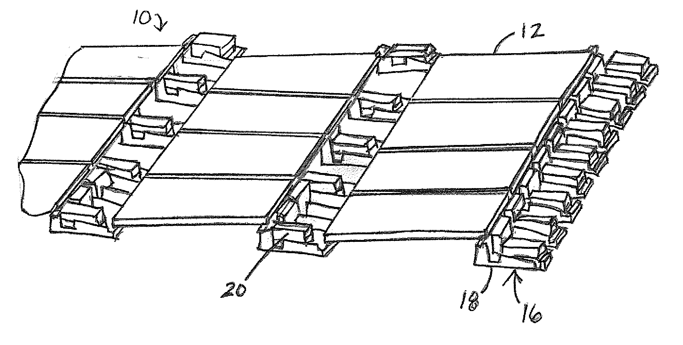
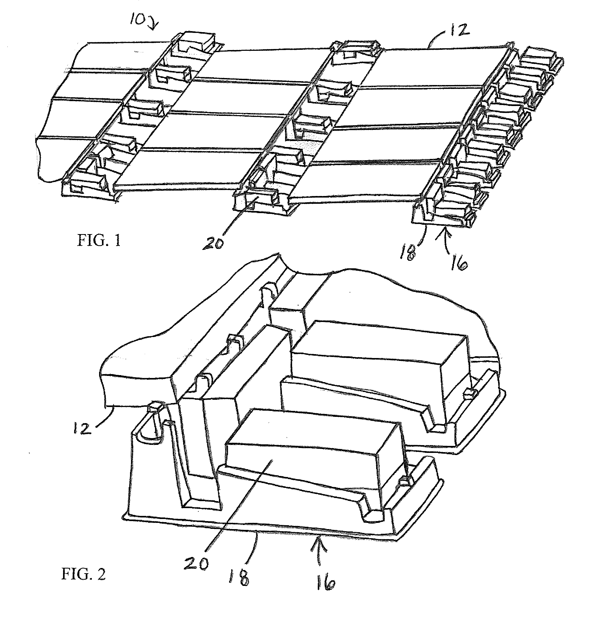
[0029]FIGS. 1 and 2 illustrate a photovoltaic system 10 according to the present invention. The illustrated photovoltaic system or array 10 includes an array of solar panels or PV modules 12 mounted to a substantially flat support surface 14 (pitch range o...


PUM


Abstract

A photovoltaic system includes a plurality of rectangular-shaped photovoltaic modules and a plurality of separate and spaced-apart support members supporting and orienting the photovoltaic modules in an array on the support surface without penetrating the support surface. The support members are formed of plastic and each of the photovoltaic modules is supported by at least four of the support members. Each of the support members is secured to and supports at least one of the photovoltaic modules but is not directly secured to any of the other support members. Thus the support modules can be utilized to support a wide variety of different sizes of photovoltaic modules. A wind shield is located at the rearward most support members. The wind shield is spaced a distance from the rearward photovoltaic modules and shaped to deflect wind up and over the array of photovoltaic modules.

Description

CROSS-REFERENCE TO RELATED APPLICATIONS[0001]This application claims the priority benefit of U.S. Provisional Patent Application No. 61 / 447,883 filed on Mar. 1, 2011, the disclosure of which is expressly incorporated herein in its entirety by reference.STATEMENT REGARDING FEDERALLY SPONSORED RESEARCH[0002]Not ApplicablePARTIES TO A JOINT RESEARCH AGREEMENT[0003]Not ApplicableREFERENCE TO APPENDIX[0004]Not ApplicableFIELD OF THE INVENTION[0005]The field of the present invention generally relates to mounting systems and methods and, more particularly, to systems and methods for mounting photovoltaic modules or panels on support surfaces such as, for example, building rooftops, the ground, or the like.BACKGROUND OF THE INVENTION[0006]A photovoltaic (PV) panel, often referred to as a solar panel or PV module, is a packaged interconnected assembly of solar cells also known as PV cells. The PV module is typically used as a component of a larger PV system to generate and supply electricity...

Claims


Application Information

Patent Timeline
Patent Type & Authority Applications(United States)
IPC IPC(8): H01L31/048
CPCY02E10/50H02S20/24H02S20/00Y02B10/12F24S25/11F24S25/16F24S25/636H02S20/10H02S20/23Y02B10/10Y02E10/47
Inventor WILDES, BRIAN
Owner UNIRAC INC
Why Eureka
Try Eureka