Method for Generating High Resolution Depth Images from Low Resolution Depth Images Using Edge Layers

a technology of depth images and edge layers, applied in the field of image processing and compression, can solve the problems of compromising the quality of virtual images, spatial monotony of depth images, and substantial redundancy between texture images and corresponding depth images, and achieve the effect of high resolution

Inactive Publication Date: 2012-10-25
MITSUBISHI ELECTRIC RES LAB INC
View PDF17 Cites 59 Cited by
  • Summary
  • Abstract
  • Description
  • Claims
  • Application Information

AI Technical Summary

Benefits of technology

[0013]The embodiments of the invention provide a method for interpolating and filtering a low resolution depth image to construct a high resolution depth image using information associated with depth discontinuities, i.e., depth edges. Each depth image includes an array of pixels at locations (x, y), and each pixel has an associated depth
[0014]In one embodiment, the low resolution depth image is up-sampled. Missing depths are interpolated by duplicating nearest-neighboring depths. A moving window is then applied to the pixels in the up-sampled depth image. A size of the window covers a set of pixels centred at each pixel. The pixels covered by each window are selected according to their relative offset to a depth discontinuity, and only pixels that are on the same side of the discontinuity of the center pixel are used for the filtering. The discontinuity information can be from the correspondent texture image, explicitly generated by an encoder, implicitly obtained through analysis of the low resolution depth image, or...

Problems solved by technology

However, MVC does not specify any particular encoding for the depth images.
There is a substantial redundancy between the texture images and the corresponding depth images, because both the texture and depth images depict the same objects in the 3D scene.
Unlike conventional images, depth images are spatially monotonous except at depth discontinuities.
Thus, decoding errors tend to be concentrated near depth discontinuities, and failure to preserve the depth discontinuities significantly compromises the quality of virtu...

Method used


Image

  • Method for Generating High Resolution Depth Images from Low Resolution Depth Images Using Edge Layers
  • Method for Generating High Resolution Depth Images from Low Resolution Depth Images Using Edge Layers
  • Method for Generating High Resolution Depth Images from Low Resolution Depth Images Using Edge Layers

Examples


embodiment 1

[0038]For some embodiments, the depth images can have a resolution lower than the resolution of the texture image. One embodiment down-samples the input depth image before encoding to improve encoding efficiency.

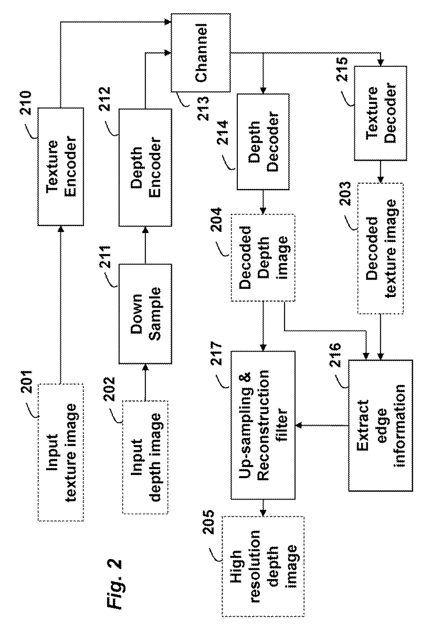
[0039]FIG. 2 shows a first embodiment of the invention to use the edge information to assist the depth up-sampling and reconstruction.

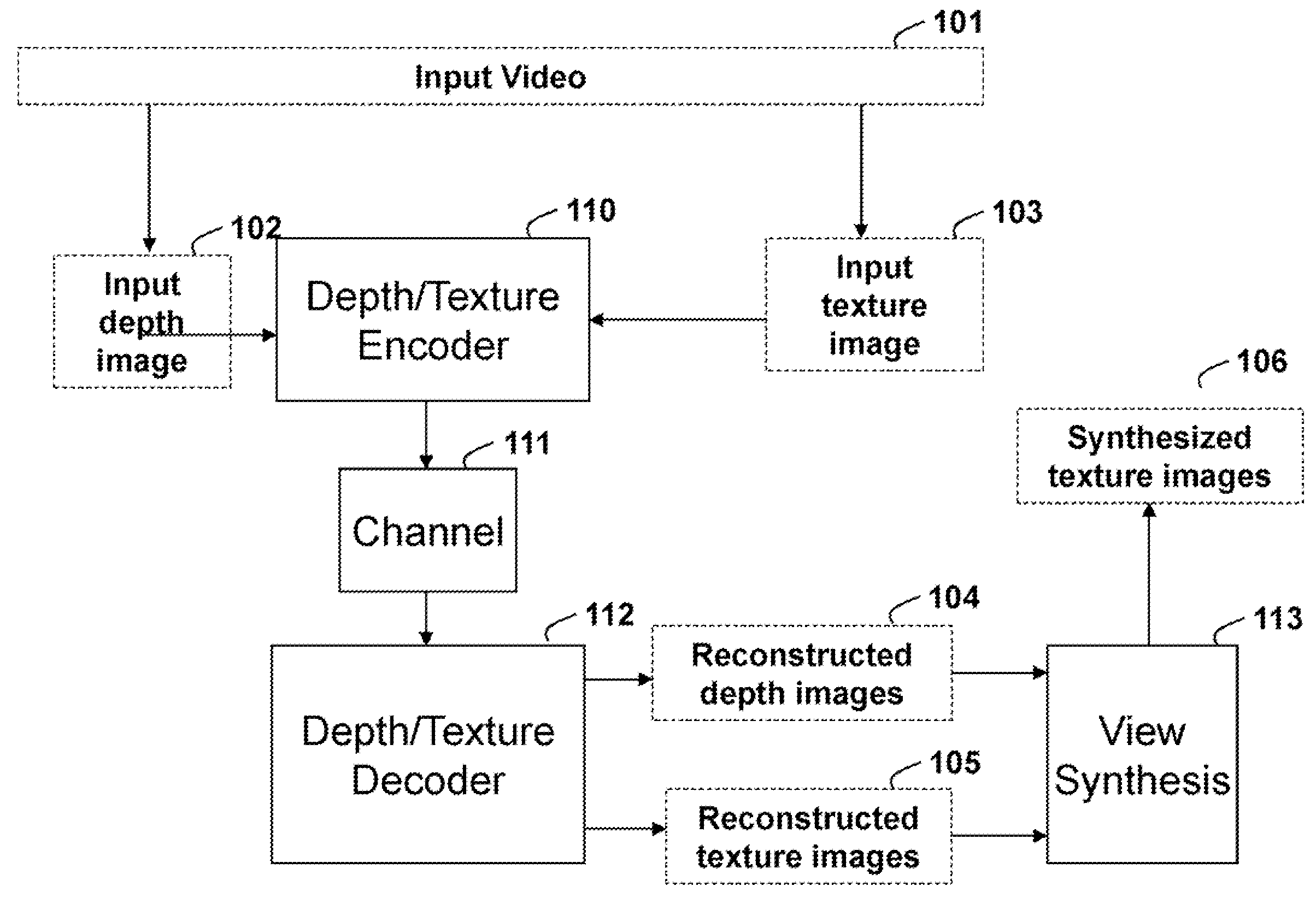
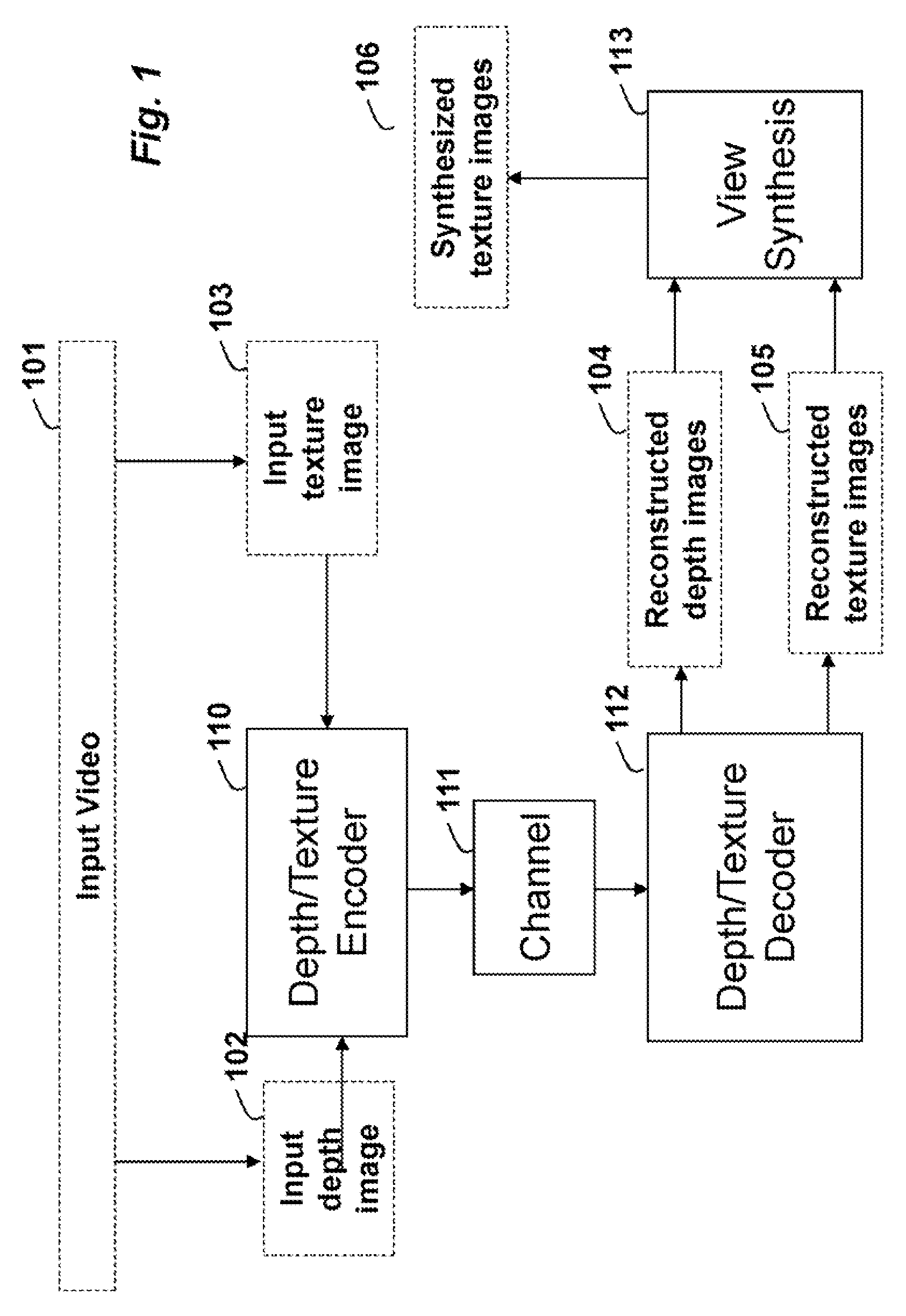
[0040]The input includes one or more texture images 201, and corresponding depth images 202. The texture images 201 are encoded 210, passed through a channel 213 and decoded 215.

[0041]Before the depth encoding 212, the high resolution depth image 202 is down-sampled 211 to reduce the resolution of the depth image. The input depth image can already be a low resolution depth image. Nevertheless, the depth image still needs to be up-sampled for view synthesis.

[0042]The low resolution depth image is coded 212 and passes through the channel 213 to a depth decoder 214. Because the decoded depth image 204 has a lower resolution, an up-sampling and re...

embodiment 2

[0045]FIG. 3 shows another embodiment. The edge information is known at the encoder, and transmitted to the decoder explicitly. The edge information 306 for the input depth image 202 can be explicitly encoded 318, transmitted through the channel 213 and decoded 319 to produce decoded edge information 307. The edge information can be used by the up-sampling and reconstruction filter 217 to separate the foreground and background region, when filtering the decoded depth image.

[0046]In both embodiment 1 and 2, the reconstruction process filters after the decoding.

embodiment 3

[0047]FIG. 4A shows an AVC decoder 400 for generating the decoded texture image 203 from the input texture bitstream 401.

[0048]FIG. 4B shows an AVC decoder 400 for generating the decoded depth image 204 from the input depth bitstream 402. The depth decoded depth image can subsequently be used to generate the high resolution depth image 205 with the up-sampling and reconstruction filter 217.

[0049]As shown in FIG. 4B, the reconstruction filter's output is no longer used by the encoder. That is the reconstructed high resolution depth image is outside the prediction loop.

[0050]A modified H.264 / AVC codec includes an encoder and a decoder for multi-view texture and the other for multi-view depth. The depth encoder and decoder use a depth up-sampling reconstruction filter according to embodiments of our invention and described herein.

[0051]Input to the encoder includes the multi-view texture input video and the corresponding sequence of multi-view depth images. Output includes encoded bits...


PUM


Abstract

A method interpolates and filters a depth image with reduced resolution to recover a high resolution depth image using edge information, wherein each depth image includes an array of pixels at locations and wherein each pixel has a depth. The reduced depth image is first up-sampled, interpolating the missing positions by repeating the nearest-neighboring depth value. Next, a moving window is applied to the pixels in the up-sampled depth image. The window covers a set of pixels centred at each pixel. The pixels covered by the window are selected according to their relative offset to the depth edge, and only pixels that are within the same side of the depth edge of the centre pixel are used for the filtering procedure.

Description

RELATED APPLICATION[0001]This is a Continuation-in-Part Application of U.S. Ser. No. 12 / 001,436, “Method for Generating High Resolution Depth Images from Low Resolution Depth Images Using Edge Information,” filed by Graziosi et al., on Feb. 5, 2012, and incorporated herein by reference.FIELD OF THE INVENTION[0002]This invention relates generally to image processing and compression, and more particularly to up-sampling and reconstruction filters applied to depth images to produce high-resolution depth images.BACKGROUND OF THE INVENTION[0003]Depth Images[0004]Depth images represent distances from a camera to a three-dimensional (3D) scene. Efficient encoding of depth images is important for 3D video, and free view television (FTV). FTV enables a user to interactively control the view and generate new virtual images of a dynamic scene from arbitrary view point.[0005]Most conventional image-based rendering (IBR) methods use the depth images, in combination with stereo or multi-image vid...

Claims


Application Information

Patent Timeline
IPC IPC(8): G06K9/32
CPCH04N19/597G06T3/403H04N19/59H04N19/20
Inventor GRAZIOSI, DANILLO B.TIAN, DONGVETRO, ANTHONY
Owner MITSUBISHI ELECTRIC RES LAB INC
Why Eureka
Try Eureka