Optimization of dead space in pistonless compressors

a dead space and compressor technology, applied in the direction of positive displacement liquid engines, pump control, non-positive displacement pumps, etc., can solve the problems of separator units, undesirable carrying along, and disadvantages described in context with common compressors, so as to increase the delivery rate of pistonless compressors and minimize specific compression energy

Inactive Publication Date: 2012-10-25
LINDE AG
View PDF2 Cites 0 Cited by
  • Summary
  • Abstract
  • Description
  • Claims
  • Application Information

AI Technical Summary

Benefits of technology

[0009]It is the object of the instant invention to specify a generic method for operating a pistonless compressor, which avoids the afore-mentioned disadvantages, in particular increases the delivery rate of a pistonless compressor and minimizes the specific compression energy.

Problems solved by technology

The disadvantages described in context with common compressors are thus still present, albeit to a lesser extent.
Presently, however, such separator units only serve the purpose of separating liquid, which was undesirably carried along, out of the compressed media flow.

Method used


Image

  • Optimization of dead space in pistonless compressors
  • Optimization of dead space in pistonless compressors

Examples


Embodiment Construction

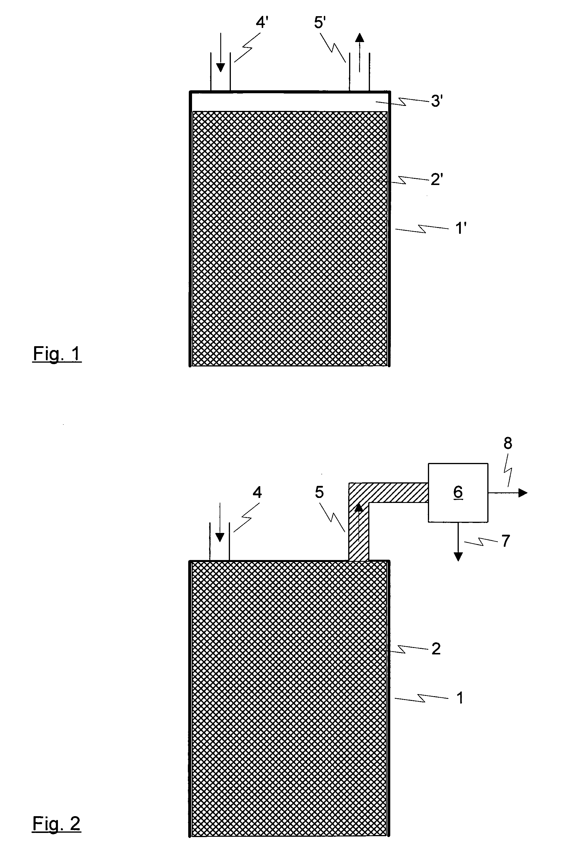
[0016]A separation of the liquid delivered in excess from the compressed medium is advantageous or required in particular when the liquid delivered in excess represents an undesired contamination in a subsequent process, to which the compressed medium is supplied. When ionic liquids are used as operating means, a separation and return of the liquid delivered in excess seems to be sensible for cost reasons as well. Furthermore, the “loss” of the liquid quantity delivered in excess, among other things, can also be accepted, in particular when a replacement of the liquid quantity delivered in excess with new operating liquids is required or desired.

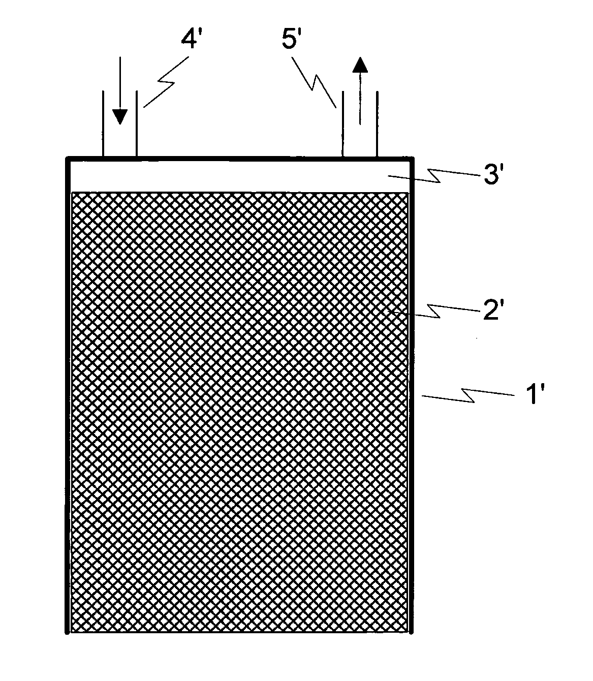
[0017]The method according to the invention for operating a pistonless compressor as well as further embodiments thereof, which represent objects of the dependent patent claims, shall be specified in detail below by means of the exemplary embodiment illustrated in FIG. 2.

[0018]As already shown in FIG. 1, FIG. 2 also shows a schematized secti...


PUM


Abstract

A method for operating a pistonless compressor, which serves the purpose of compressing a gaseous medium, in particular a cryogenic medium and in the cylinder of which a liquid column is moved up and down, is described.

Description

CROSS REFERENCE TO RELATED APPLICATIONS[0001]The present application claims priority from German patent application DE 1020060143, filed Mar. 28, 2006, and Patent Cooperation Treaty application PCT / EP2007 / 001912 filed Mar. 6, 2007.BACKGROUND OF THE INVENTION[0002]The invention relates to a method for operating a pistonless compressor, which serves the purpose of compressing a gaseous medium, in particular a cryogenic medium and in the cylinder of which a liquid column is moved up and down.[0003]The term “pistonless compressor” is to be understood to be a compressor and a device for compressing a gaseous medium, respectively, as it / they is / are disclosed in PCT patent application PCT / EP2005 / 008370. Such devices are identified as “pistonless compressors”, because a liquid column instead of a fixed piston is moved up and down therein. For a short time, ionic liquids are also being used as liquids for such compressors. They have a plurality of advantages, as they are also disclosed in th...

Claims


Application Information

Patent Timeline
Patent Type & Authority Applications(United States)
IPC IPC(8): F04B41/00
CPCF04F1/06
Inventor ADLER, ROBERTSIEBERT, GEORGMAYER, HELMUT
Owner LINDE AG
Why Eureka
Try Eureka