Kinetic rocking toy

Inactive Publication Date: 2012-11-01
SANTARSIERO PAUL
View PDF36 Cites 14 Cited by
  • Summary
  • Abstract
  • Description
  • Claims
  • Application Information

AI Technical Summary

Benefits of technology

[0023]The present invention relates to a Kinetic reconfigurable modular structure having interconnected hollow track sub-components and motioning ball or device(s) within. This assembled device raises up off the ground plane and has several modular embodiments wherein each of these embodiments allows the assembled structure to rock and motion. If enough inertia is extended on it a full roll may result when the structure is placed on a flat surface such as the floor. This Kinetic Rocking Device allows for full 360-degree axial connection options for the end-user, which is the reason the modules assemble into a varety of end structures.

Problems solved by technology

It is well known that pets which are bored can exhibit destructive behavior such as chewing on furniture, urinating indoors and in inappropriate places, excessive noise making, etc. which the pet naturally uses to communicate and to vent their frustration.
It is also well known that bored and under-engaged Infants suffer from slower cognitive development due to lack of human and environmental stimulus.

Method used


Image

  • Kinetic rocking toy
  • Kinetic rocking toy
  • Kinetic rocking toy

Examples


Embodiment Construction

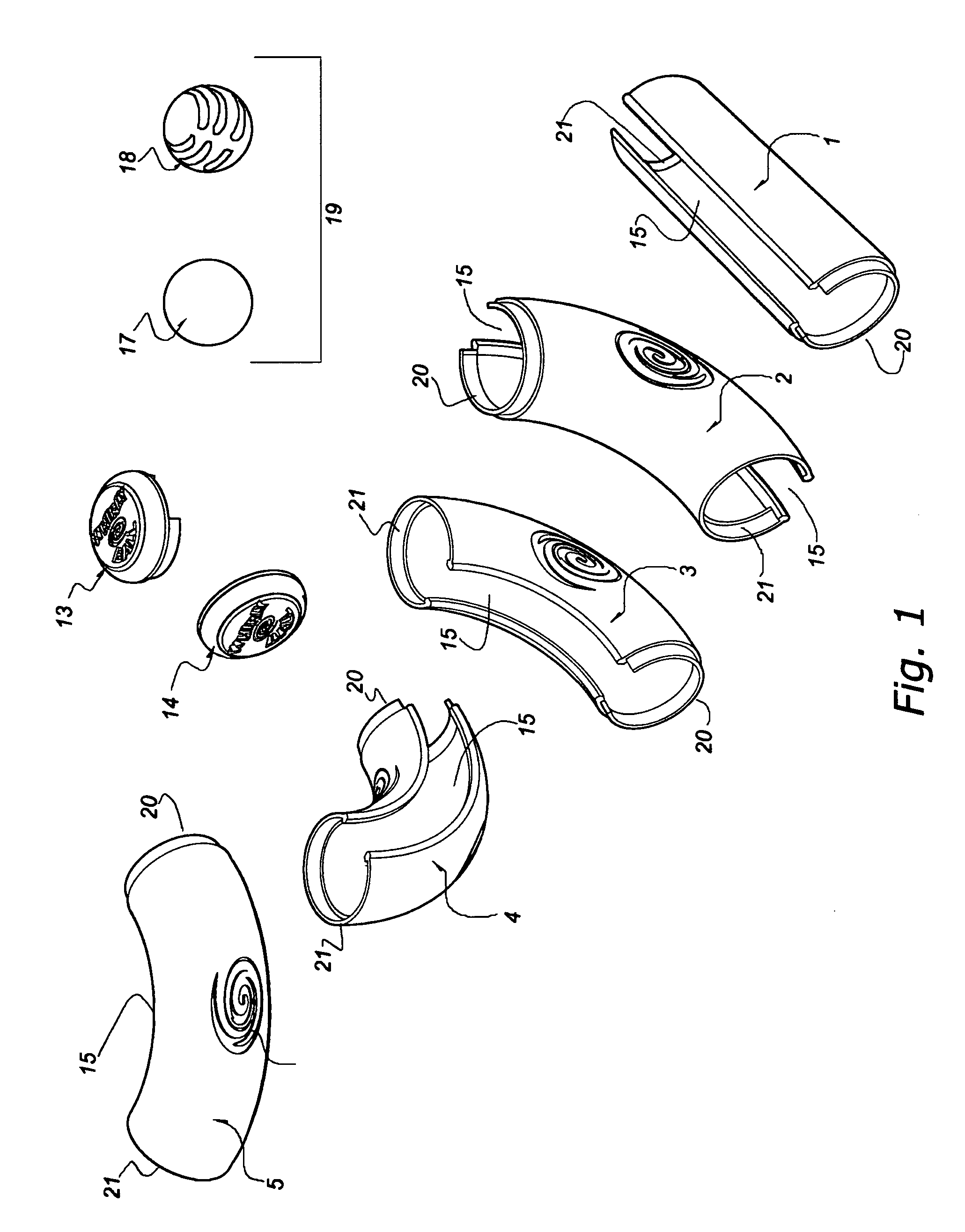
[0024]FIG. 1 is a perspective view of the modular components having a full slotted opening which allows uninterrupted access to the ball or device inside. These modules have a friction fit And snap assembly where the outer ends intersect into one another.

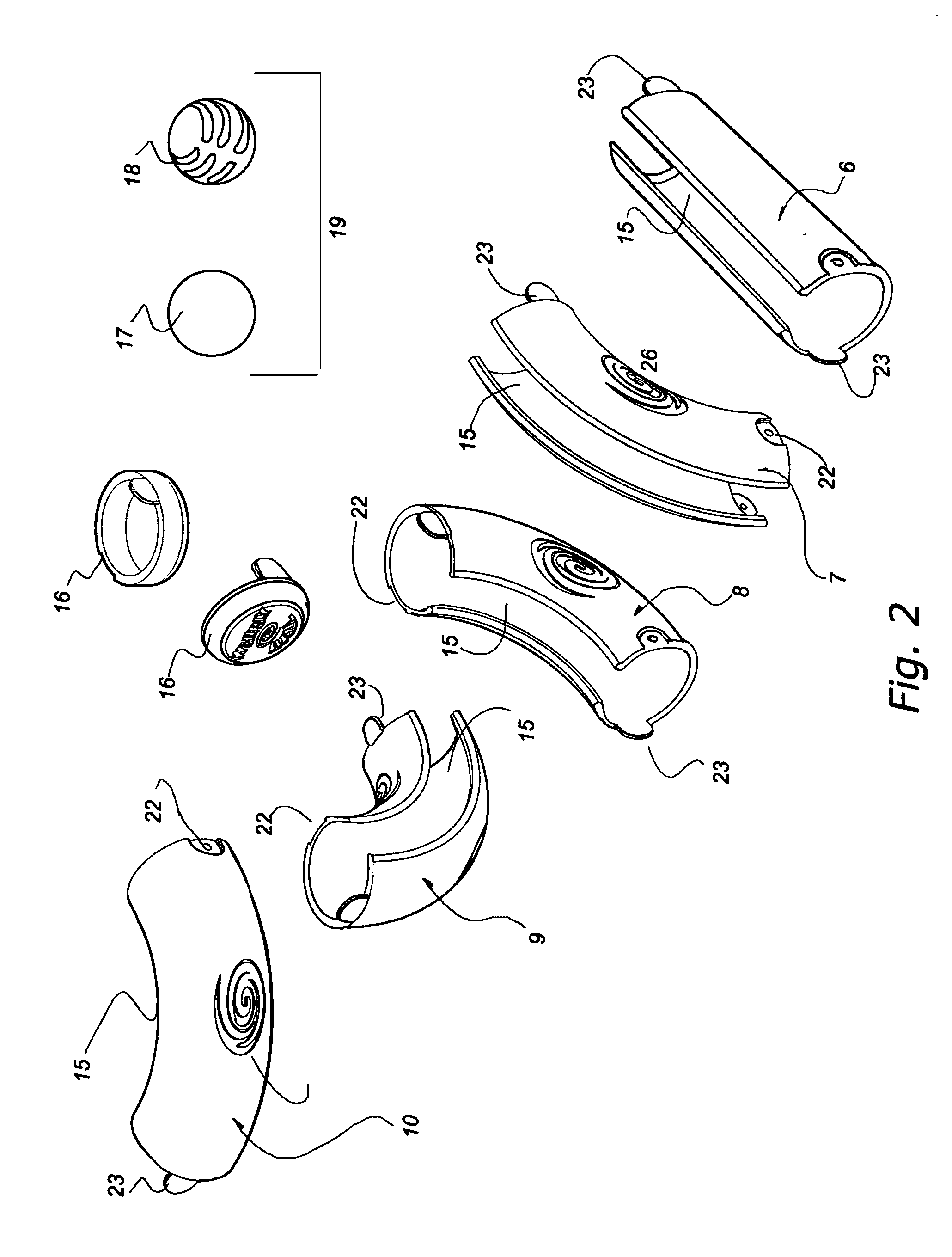
[0025]FIG. 2 is a perspective view of the of the modular components showing 2 modules which snap together having twin raised taps and negative receiving voids for these on the opposite side to allow part to be assembled in a series.

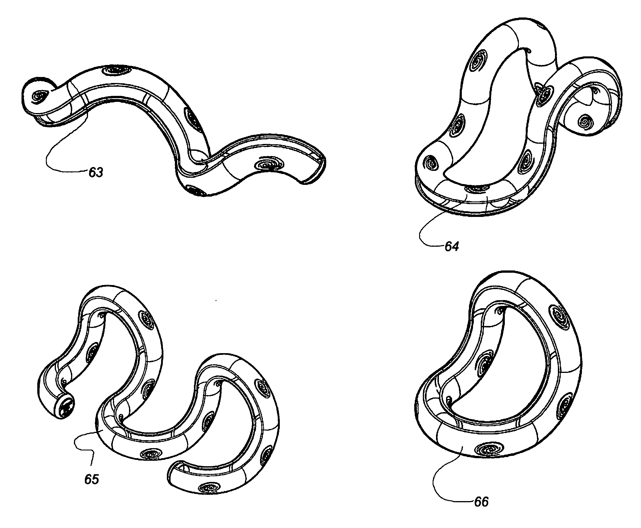
[0026]FIG. 3 is a perspective view of the of the modular components having a segmented slotted openings which does not allow for full access to the ball or device inside

[0027]These modules snap together having twin extending taps on one side of the part and which has 4 pairs of receiving slots on the opposite side of the part to accept the extension tabs from the next modular part.

[0028]FIG. 1 is a perspective view illustrating 8 unique subcomponents of a semicircular module engagement design.

[0029]FIG. 3...


PUM


Abstract

A Kinetic, reconfigurable modular structure having hollow track sub-components and an internal motioning device(s). The invention employs multiples of 1-5 unique modular hollow track part(s), each connecting to one another. A more basic version would use one repeatable, multi-positional modular track part. Both versions employ at least one internal motioning device(s). These modules connect securely to one another to create a multitude of 3-dimensional, rollercoaster-like tubular structures. The outer structure along with the internal motioning device(s) will easily rock or roll to and fro. The track modules assemble to create end-to-end structures or continuous loop structures where the internal device navigates throughout the structure. A continuous slot can be incorporated into the track modules to allow for unobstructed contact with the internal device. The internal device(s) can be battery powered thus allowing for self-propelled motion, vibration, sound, and / or lights. The integration of a motion sensor would automatically trigger these electronics.

Description

CROSS-REFERENC TO RELATED APPLICATION[0001]This application claims the benefit of the U.S. Provisional Patent Application No. 61 / 479,687, entitled KINETIC ROCKING DEVICE and filed, in the name of the inventor hereof, on Apr. 27, 2011.BACKGROUND OF THE INVENTION[0002]It is well known that Cats enjoy to be stimulated by motioning objects and toys and there are many options for the consumer to buy to entertain their small pet(s). The following United States patent documents represent prior art that could be considered germane to the present invention:[0003]U.S. Pat. No. 7,806,087[0004]U.S. Patent No. 20100058994A1[0005]U.S. Patent No. 20100258060A1[0006]U.S. Patent No. 20090308328A1[0007]U.S. Patent No. 20080011244A1[0008]U.S. Patent No. 20080141947A1[0009]U.S. Patent No. 20080083378A1[0010]U.S. Pat. No. 7,854,688[0011]U.S. Pat. No. 5,870,971[0012]U.S. Pat. No. 5,924,908[0013]U.S. Pat. No. 5,809,938[0014]U.S. Pat. No. 5,529,017[0015]U.S. Pat. No. 5,544,623[0016]U.S. Pat. No. 5,572,955[...

Claims


Application Information

Patent Timeline
IPC IPC(8): A01K29/00A01K15/02
CPCA01K15/025A63H33/062A63F7/3622A63F2009/2447A63F2007/3625A63F2007/3662A63F7/386
Inventor SANTARSIERO, PAUL
Owner SANTARSIERO PAUL
Why Eureka
Try Eureka