Modular pallet structure

a pallet structure and module technology, applied in the field of pallet structures, can solve the problems of inconvenience for the business which uses, cost (including the cost of interruption of operations), and the general inability of pallets to meet the needs of small lifting operations

Inactive Publication Date: 2001-03-13
CODDINGTON LEIGH
View PDF17 Cites 58 Cited by
  • Summary
  • Abstract
  • Description
  • Claims
  • Application Information

AI Technical Summary

Problems solved by technology

Particularly after an extended period of use, the constructional configuration of such pallets, and the material from which they are made (ie. generally wood), either alone in combination, results in them breaking.
When that occurs, it is necessary for them to be replaced, which results in cost (including the cost of interruption of operations) as well as inconvenience to the business which uses them.
Such pallets are therefore generally not suited to smaller scale lifting operations.
Conventional pallets of the type previously described are completely unsuitable for such operations.
This procedure is not as efficient as it could be, as it frequently requires the original load to be carried on conventional (large) pallets, which (i) must either be removed from the vehicle transporting them to enable the load to be divided, or alternatively (ii) the load must be divided on the vehicle and transferred to the other vehicles involved.
This is not possible with conventional pallets.
In addition, when traditional wooden pallets are not in use, their storage generally requires a considerable amount of space.
As under-cover storage costs are generally high nowadays, typically, this means that such pallets are stored outside, and are therefore exposed to the elements.
In the case of the wooden pallets. their exposure to the degrading forces of rain and the heat from sunshine only serves to deteriorate their structural integrity all the more.
In turn, this increases the possibility of the pallet breaking, over the passage of time.
In addition, conventional pallets are generally stand-alone structures, and are not adapted in use, to engage other pallets so as to form larger load-bearing structures.
This operational inflexibility of the conventional pallet is often disadvantageous, particularly where it is desired to use a pallet so as to create a larger load-bearing structure or surface, such as a platform.

Method used


Image

  • Modular pallet structure
  • Modular pallet structure
  • Modular pallet structure

Examples


Embodiment Construction

Preferred embodiments of the present invention will now be described by way of example only, with reference to the accompanying drawings, in which:

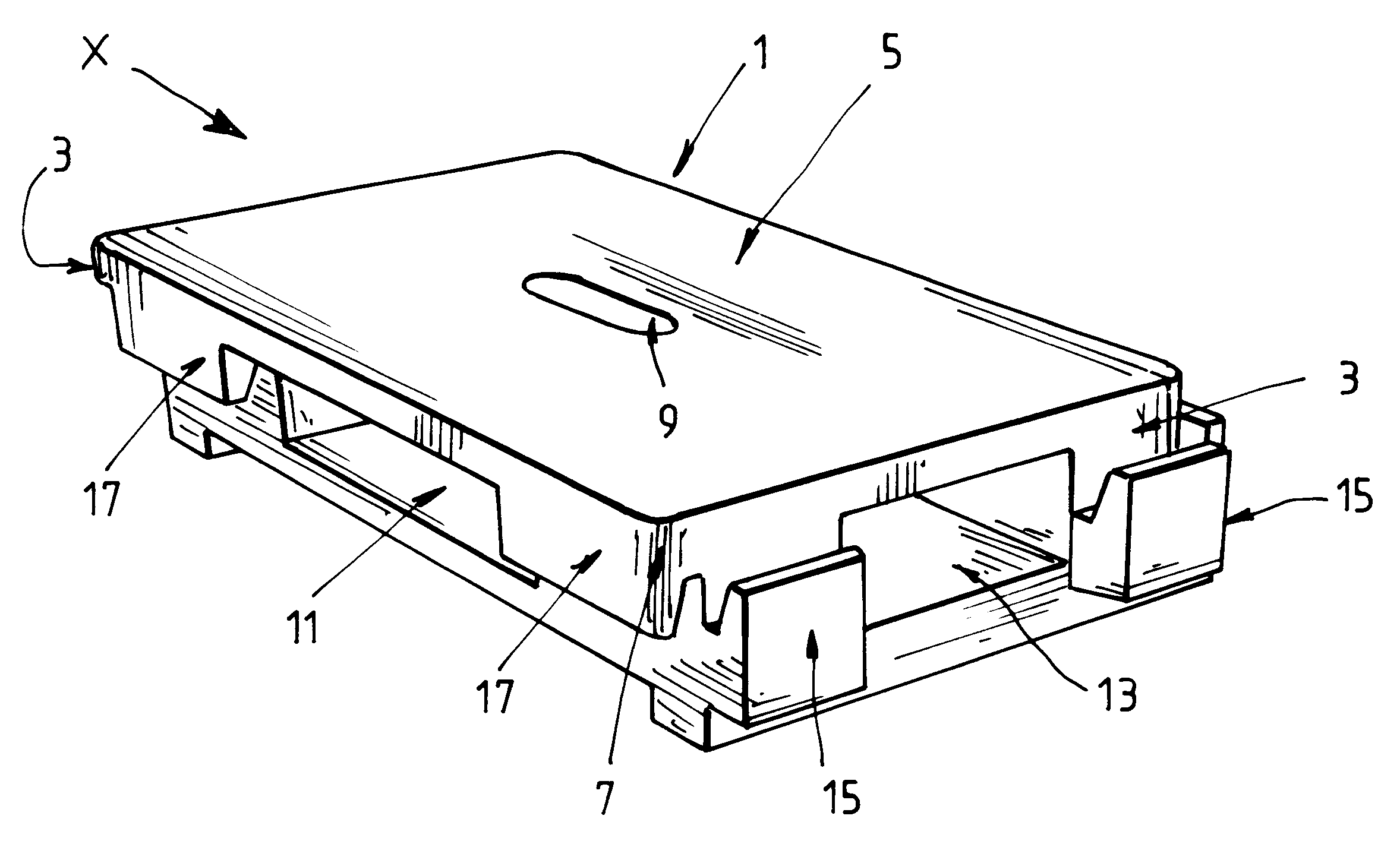
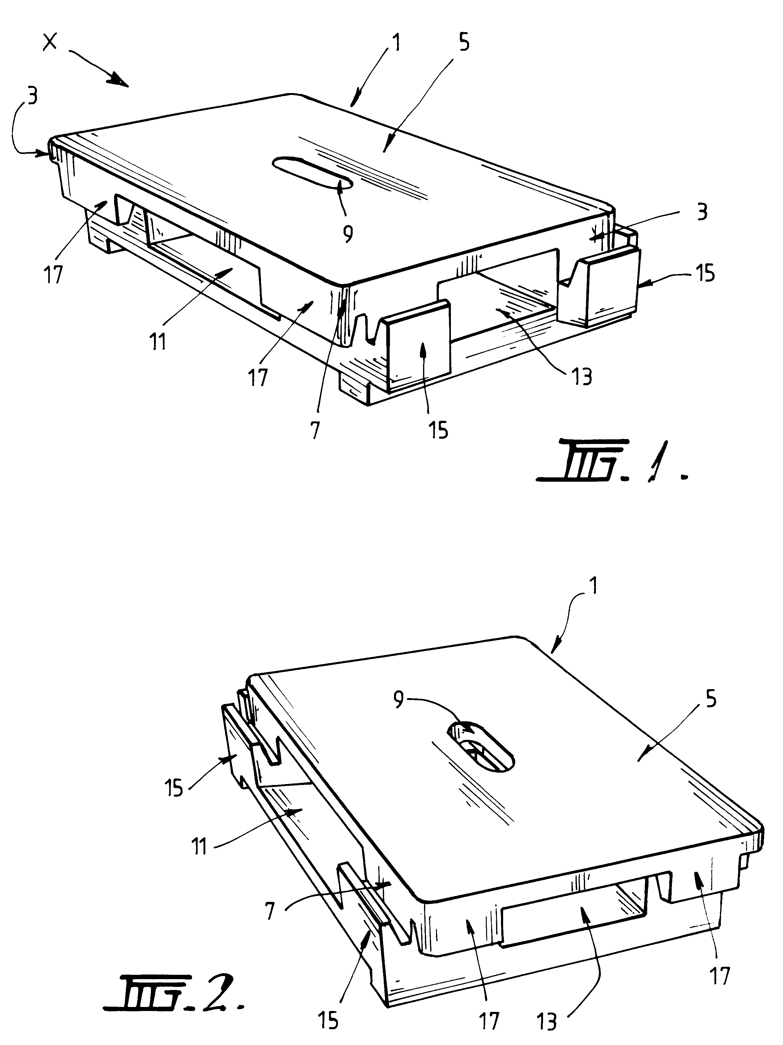
FIG. 1 represents a perspective view of a modular pallet structure constructed in accordance with the present invention;

FIG. 2 represents a perspective view of the structure shown in FIG. 1, when viewed generally in the direction of the line "X" in FIG. 1;

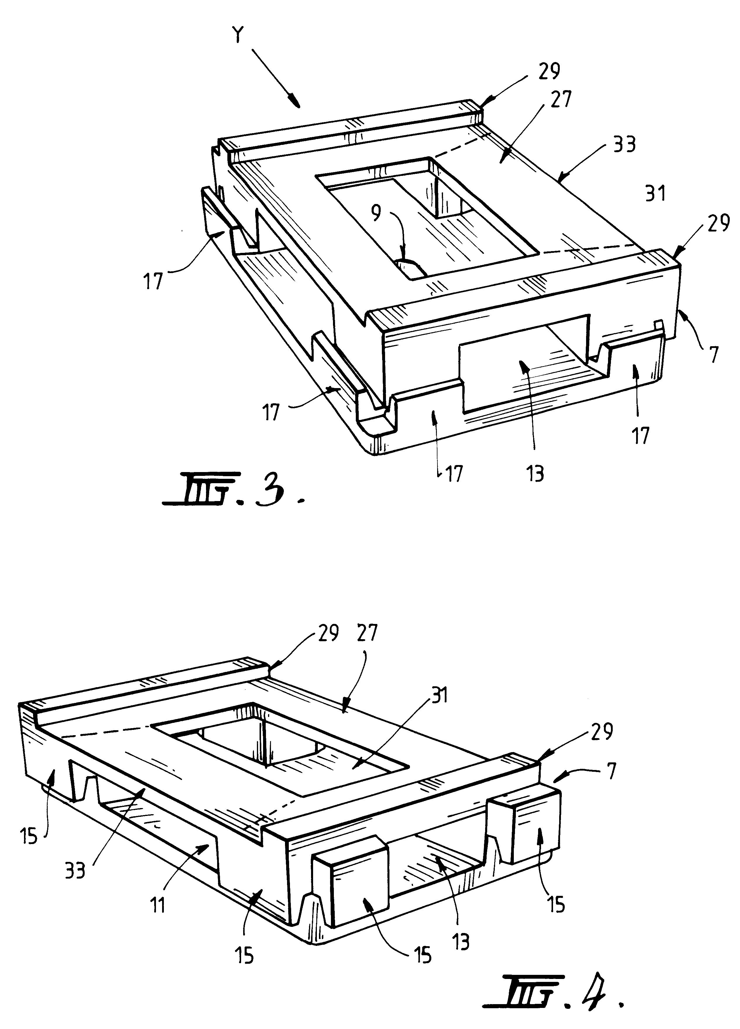
FIG. 3 is a perspective view from underneath of the structure shown in FIG. 1;

FIG. 4 is a further underneath perspective view of that structure, when viewed generally in the direction of the line "Y" in FIG. 1;

FIG. 5 is a plan view from above of the structure shown in FIG. 1;

FIG. 6 is a plan view of the structure from underneath;

FIG. 7 is a side elevation of the structure shown in FIG. 1 when viewed in the direction of the arrow A shown in FIG. 5;

FIG. 8 is a side elevation of the structure when viewed in the direction of the arrow B shown in FIG. 5;

FIG. 9 is an end elevation of the struc...


PUM


Abstract

The disclosure provides a modular structure, the structure including an upper platform and an underlying support element and structure is provided on at least one peripheral side of the upper platform or the support element for releasably engaging a reciprocal structure on another unit of the structure.

Description

This invention relates to modular structures and methods for forming larger structures from them. One use to which the invention is particularly (although not exclusively) applicable is in relation to pallets and operations which utilise pallet or load-bearing structures. Accordingly, while the invention is of more general application, the background to the invention will be discussed particularly in relation to pallet technology.BACKGROUND TO THE INVENTIONConventional pallet structures suffer from a number of shortcomings. To date, pallets used in warehousing, transportation and storage operations have often been constructed in such a way, and from materials which are in appropriate to lending them to repeated use. For example, conventional pallets have traditionally taken the form of generally open enclosures which are made from wooden slats. Pallet structures of this nature have been used in storage, transportation and warehousing operations for many years. Particularly after an ...

Claims


Application Information

Patent Timeline
Patent Type & Authority Patents(United States)
IPC IPC(8): B65D19/00B65D19/26B65D19/32
CPCB65D19/0016B65D2519/00024B65D2519/00029B65D2519/00034B65D2519/00059B65D2519/00064B65D2519/00069B65D2519/00268B65D2519/00288B65D2519/00293B65D2519/00318B65D2519/00323B65D2519/00333B65D2519/00552B65D2519/00567B65D2519/0094B65D2519/0096B65D2519/00791
Inventor CODDINGTON, LEIGH
Owner CODDINGTON LEIGH
Why Eureka
Try Eureka