Method and apparatus for continuously detecting the presence of vehicles, with an optical sensor and a magnetic sensor

a technology of optical sensors and magnetic sensors, applied in the detection of traffic movement, traffic control systems, instruments, etc., can solve the problems of inability to detect stationary vehicles, and complex solutions, so as to reduce energy consumption and reduce energy consumption

Inactive Publication Date: 2012-11-01
UNIV POLITECNICA DE CATALUNYA
View PDF6 Cites 15 Cited by
  • Summary
  • Abstract
  • Description
  • Claims
  • Application Information

AI Technical Summary

Benefits of technology

[0018]To reduce the energy consumption, when the digital controller changes state it selects the clock frequency most appropriate for the tasks it has to perform in that new state. Thus, for example, in stand-by for an interrupt in EI, all the clock oscillators are stopped; in the intervals between the measurements of B, a low frequency clock is selected, while for the measurement of B and the communication of signals a high frequency clock is selected. Also to reduce energy consumption, the interface circuits of the op...

Problems solved by technology

This solution is technically more complex, since it is necessary to be able to detect vehicles which are partly or completely hidden behind others, and it requires having a support for mounting the camera or cameras.
It will be appreciated that, like happens with the piezoelectric sensors, pneumatic tubes and inductive coils, which detect a short transitory change due to the passage of the vehicle, this sensor has to be continuously in the active state, with the consequent energy consumption, and cannot detect stationary vehicles.
One problem common to all these applications based on magnetoresistors is that the energy consumption of these sen...

Method used


Image

  • Method and apparatus for continuously detecting the presence of vehicles, with an optical sensor and a magnetic sensor
  • Method and apparatus for continuously detecting the presence of vehicles, with an optical sensor and a magnetic sensor
  • Method and apparatus for continuously detecting the presence of vehicles, with an optical sensor and a magnetic sensor

Examples


Embodiment Construction

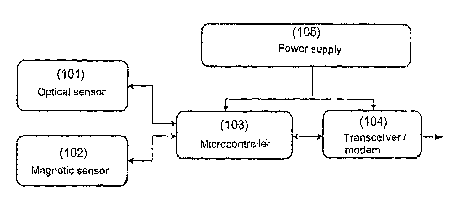
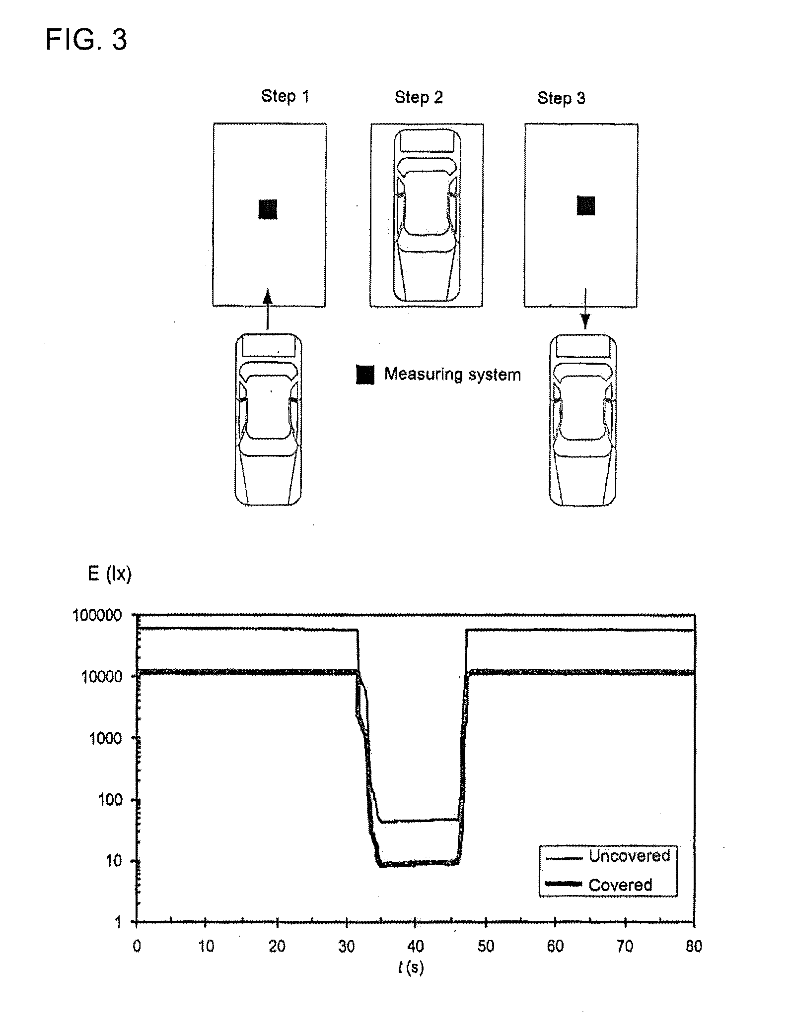
[0012]We have developed a new method and apparatus for detecting whether there is a vehicle present in a predetermined area, by way of a detector disposed in the flooring of the area it is desired to control, and which consists of a passive optical sensor detecting the shade produced by the vehicle, and from which information there is controlled the supply to, and the measuring by, a magnetoresistive sensor which confirms whether said shade is due to a vehicle which is over the sensor or, on the contrary, the illumination has been reduced for other reasons. The detector may be fixed or portable, wireless or connected by cables, and may operate independently or as part of a sensor network.

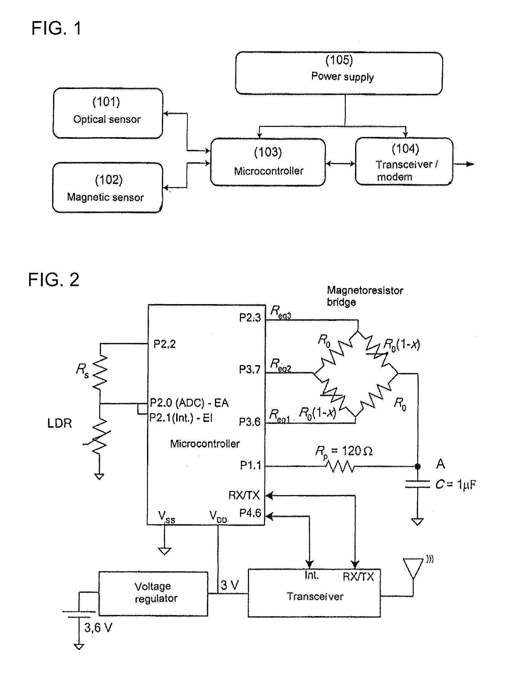
[0013]The apparatus developed is based on a digital controller to which a passive optical sensor and a magnetic sensor are connected, by way of the corresponding electronic interfaces, a communications circuit (transceiver or modem) and a supply system supplying current to the controller and to the ...


PUM


Abstract

A method and apparatus for continuous, non-intermittent, detection of vehicles based on a light detector for detecting a change in illumination when a vehicle arrives or departs, and on a use of the light detection to activate a magnetic sensor, a sensitivity of which is adjusted to detect only those magnetic disturbances sufficiently large to be able to be attributed to a vehicle which is over the sensor. Both the light detector and the magnetic sensor are connected directly to a digital controller without a need for active electronic components or their own or a shared power supply source. The light detector may be fixed or portable, wireless or connected by cables, and may operate independently or as part of a sensor network.

Description

[0001]This application claims the benefit under U.S.C. Section 371, of PCT International Application No. PCT / ES2010 / 000364, filed Aug. 31, 2010 and Spanish Patent Application No. 200901970 filed Sep. 28, 2009, the contents of which are incorporated herein by reference.[0002]The present invention relates to a method and an apparatus for ascertaining whether a vehicle is present in a particular area, more particularly to a method based on a level of illumination sensor and a magnetic sensor disposed in the flooring in said area.OBJECT[0003]The object of the present invention is to develop a method for continuously detecting whether a vehicle is present in a predetermined area, using therefore a passive optical sensor which detects the shade condition produced by the vehicle and a magnetic sensor which confirms whether said shade condition is due to a vehicle which is over the sensor, or that it may be due to another cause reducing the level of illumination. A second object of the pres...

Claims


Application Information

Patent Timeline
IPC IPC(8): G08G1/042G08G1/04
CPCG01V11/00G08G1/042G08G1/04G08G1/017
Inventor PALLAS ARENY, RAMONCASAS PIEDRAFITA, JAIME OSCARSIFUENTES DE LA HOYA, ERNESTO
Owner UNIV POLITECNICA DE CATALUNYA
Why Eureka
Try Eureka