Eureka AIR delivers breakthrough ideas for toughest innovation challenges, trusted by R&D personnel around the world.

Generating uplink signals from user equipment nodes to identify interferers to a network node

Active Publication Date: 2012-11-01
TELEFON AB LM ERICSSON (PUBL)
View PDF9 Cites 39 Cited by
  • Summary
  • Abstract
  • Description
  • Claims
  • Application Information

AI Technical Summary

Benefits of technology

[0037]Accordingly, the problems described above may be overcome because the particular UE(s) which is causing interference to a network node is identified using uplink transmissions from the UE(s). Those particular UE(s) can then be controlled to reduce uplink interference to the network node. In this manner, the source of particular interference can be identified and managed, which may allow reduced interference between overlapping cells and / or more efficient frequency reuse between overlapping cells.
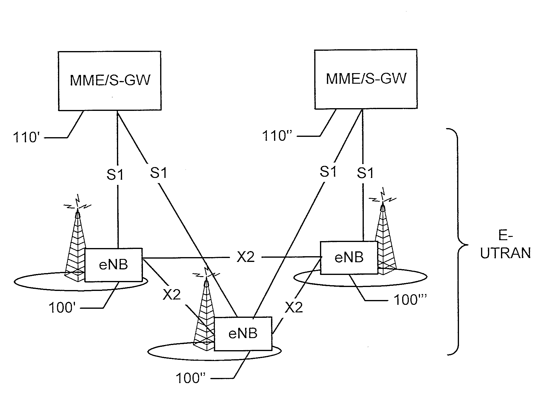
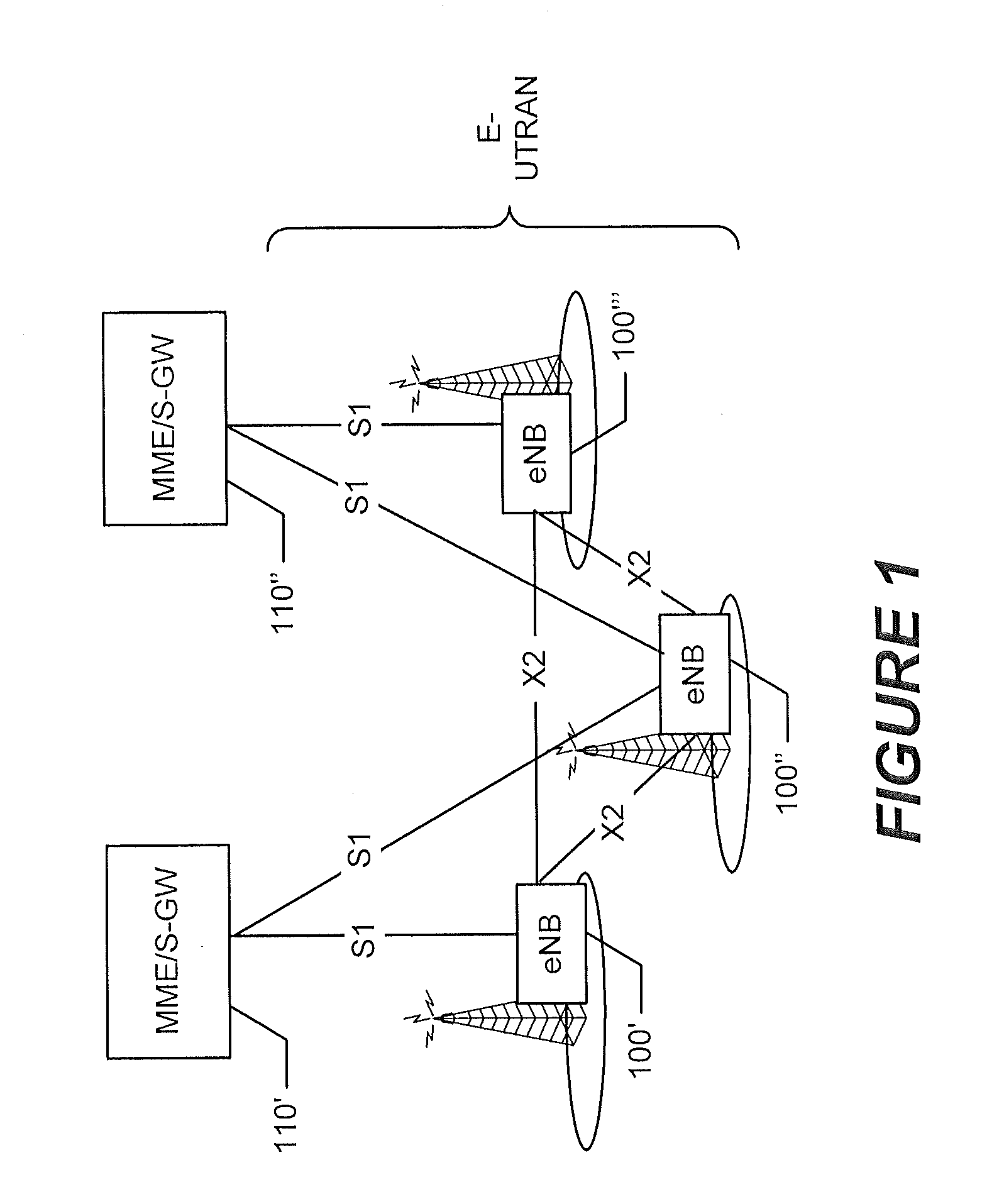
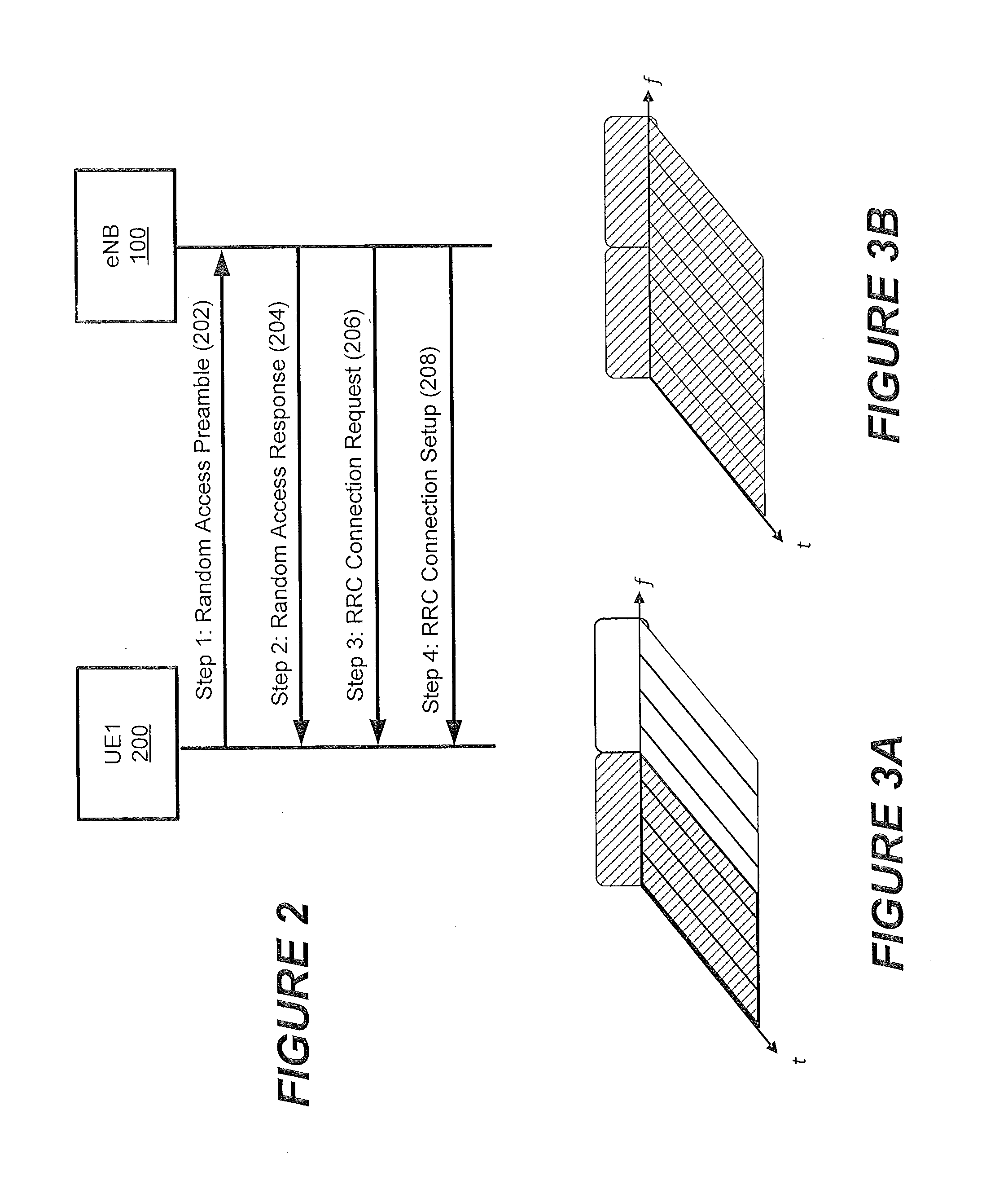
[0040]Another embodiment of the present invention is directed to a first network node, such as a serving network node, of a wireless communications network. The first network node includes a network interface, at least one transceiver, and a processor. The network interface is configured to communicate with a second network node. The transceiver is configured to communicate with a UE. The processor is configured to receive an interference message from the second network node reporting uplink interference detected by the second network node, and to initiate transmission by the UE of an uplink signal having a defined configuration, responsive to the interference message. The processor receives an uplink signal message from the second network node reporting receipt of the uplink signal transmitted by the UE, and identifies the UE responsive to the uplink signal message as being a contributor to the uplink interference. The processor controls uplink transmission by the UE and / or another UE communicating with the at least one transceiver to reduce uplink interference.

Problems solved by technology

Prediction errors, due to imperfections in map and building data, have necessitated that operators perform drive / walk tests to completely exhaust the coverage region and identify all handover regions.
When a UE served by a high power (macro) base station is closely spaced to a femto base station, possibly with restricted access, then the femto base station may induce significant downlink interference to the UE.
Nevertheless, the secondary carrier allocated to the UE could be free from interference from the femto base station, but its use could cause high interference to the femto base station cell.
However, it is not always possible to identify this interference relation based on downlink measurements.
In heterogeneous networks, it is possible that a UE served by a high power (macro) eNB may induce significant interference to a low power base station even without detecting the downlink from the low power base station.

Method used


Image

  • Generating uplink signals from user equipment nodes to identify interferers to a network node
  • Generating uplink signals from user equipment nodes to identify interferers to a network node
  • Generating uplink signals from user equipment nodes to identify interferers to a network node

Examples


Embodiment Construction

[0056]In the following detailed description, numerous specific details are set forth in order to provide a thorough understanding of the invention. However, it will be understood by those skilled in the art that the present invention may be practiced without these specific details. In other instances, well-known methods, procedures, components and circuits have not been described in detail so as not to obscure the present invention.

[0057]The following example embodiments provide a number of advantages and benefits relative to existing systems and methods for managing uplink interference by a UE to a network node. It will be appreciated by those skilled in the art in view of the present description, however, that the invention is not limited to these embodiments which produce any or all of these advantages or benefits and that other advantages and benefits may be realized depending upon the particular implementation.

[0058]Various embodiments of the present invention are directed to u...


PUM


Abstract

A method is disclosed that can be performed in at least one network node which provides wireless communications service for user equipment nodes (UEs). The method includes detecting uplink interference at an interfered network node. Responsive to the uplink interference, an uplink transmission having a defined configuration is initiated from a UE, which is served by a serving network node. The uplink signal is detected using the defined configuration at the interfered network node. The UE is identified responsive to the detected uplink signal as being a contributor to the uplink interference. An uplink transmission by the UE and / or by another UE served by the serving network node is controlled to reduce uplink interference.

Description

RELATED APPLICATIONS[0001]The present application claims the benefit of priority from U.S. Provisional Application No. 61 / 480,655 entitled “Carrier Based Uplink Interferer Identification” filed Apr. 29, 2011, the disclosure of which is hereby incorporated herein in its entirety by reference.TECHNICAL FIELD[0002]The present invention relates to wireless communication systems and, more particularly, to management of interference by user equipment nodes to network nodes.BACKGROUND[0003]Interference management is an important aspect of radio resource management mechanisms in wireless communication systems. Interference may be suppressed by signal processing and / or avoided by assigning resources in an controlled manner to avoid / suppress interference. Mechanisms for interference management can be distributed to radio network nodes of the communication system, in which case information may be shared therebetween to avoid / suppress interference between the network nodes and / or between user e...

Claims


Application Information

Patent Timeline
IPC IPC(8): H04W72/04
CPCH04W72/0413H04W28/048H04L1/0006H04W72/082H04W28/04H04W72/21H04W72/541
Inventor GUNNARSSON, FREDRIKCENTONZA, ANGELOFADAKI, MOJGANMILDH, GUNNARTEYEB, OUMERVOLTOLINA, ELENA
Owner TELEFON AB LM ERICSSON (PUBL)
Why Eureka
Eureka Blog
Learn More