Ferrofluid control and sample collection for microfluidic application

a microfluidic and fluorofluidic technology, applied in the direction of positive displacement liquid engines, pumping, machines/engines, etc., can solve the problems of large equipment and hose assemblies, red blood cells are very sensitive to mechanical pressure, and the risk of damage to blood cells is high

Inactive Publication Date: 2012-11-01
SEMICON COMPONENTS IND LLC
View PDF12 Cites 33 Cited by
  • Summary
  • Abstract
  • Description
  • Claims
  • Application Information

AI Technical Summary

Problems solved by technology

Large pieces of equipment and hose assemblies are undesirable because they can consume large amounts of energy and occupy a significant amount of workspace, among other reasons.
Conventional pneumatic, mechanical, and electromechanical systems for pumping fluids have additional drawbacks when used in certain medical applications.
Red blood cells are very sensitive to mechanical pressure, however, and can be destroyed by excessive pressure on the tubing.
Conventional peristaltic pumps used with heart machines compress and constrict tubing that carries the blood cells, creating a risk of damage to the blood cells.
Some fluid products chemically react with materials used in pumps and valves, making conventional pumps and valves inadequate.
Conventional heat transfer systems, like heat pipes that circulate water, ethanol, acetone, sodium, or mercury, suffer drawbacks because they require expensive materials and have limited application.

Method used


Image

  • Ferrofluid control and sample collection for microfluidic application
  • Ferrofluid control and sample collection for microfluidic application
  • Ferrofluid control and sample collection for microfluidic application

Examples


example 1

Fluid Driven Membrane Pump and Valve

[0037]Referring to FIG. 6, a fluid driven pump 300 is shown in accordance with another embodiment of the invention. Pump 300 includes a cluster of flexible conduits 310 placed around a central flexible tube 320 containing a ferrofluid 322. An electromagnet 350 is placed externally to the flow conduits 310 and flexible tube 320. Electromagnet 350 is ring shaped and surrounds a section of the length of the conduits 310. A magnetic field is applied through the conduits 310 to interact with the ferrofluid 322. The magnetic field properties are selected through known techniques to pull ferric particles 324 in the ferrofluid in a radial outward direction. This creates a circular pressurized “wave” of ferrofluid that exerts radial outward pressure on the wall 321 of flexible tube 320. The pressure is sufficient to constrict the diameters of each of the flexible conduits 310 and displace fluid in the conduits.

[0038]Fluid is transported through the conduit...

example 2

Fluid Driven Membrane Pump and Valve

[0040]FIG. 7 shows a pump and valve system 400 similar to Example 1, except that the system uses a flexible tube 410 surrounded by a single pipe 420. Flexible tube 410 contains a ferrofluid 412, and pipe 420 is filled with a gas or liquid 422. A source of magnetic field in the form of an electromagnet 450 is positioned around the exterior of pipe 420. Electromagnet 450 is ring shaped and surrounds a section of the length of pipe 420. A magnetic field is applied through pipe 420 to interact with ferrofluid 412. The magnetic field properties are selected through known techniques to pull ferric particles in the ferrofluid in a radial outward direction. This creates a circular wave of ferrofluid that exerts a radially outward pressure on the wall of flexible tube 410. The outward pressure on tube 410 expands the tube wall 411, constricting and reducing the surrounding area in pipe 420. The ferrofluid wave is driven in a given axial direction along the...

example 3

Pressure Surge Control

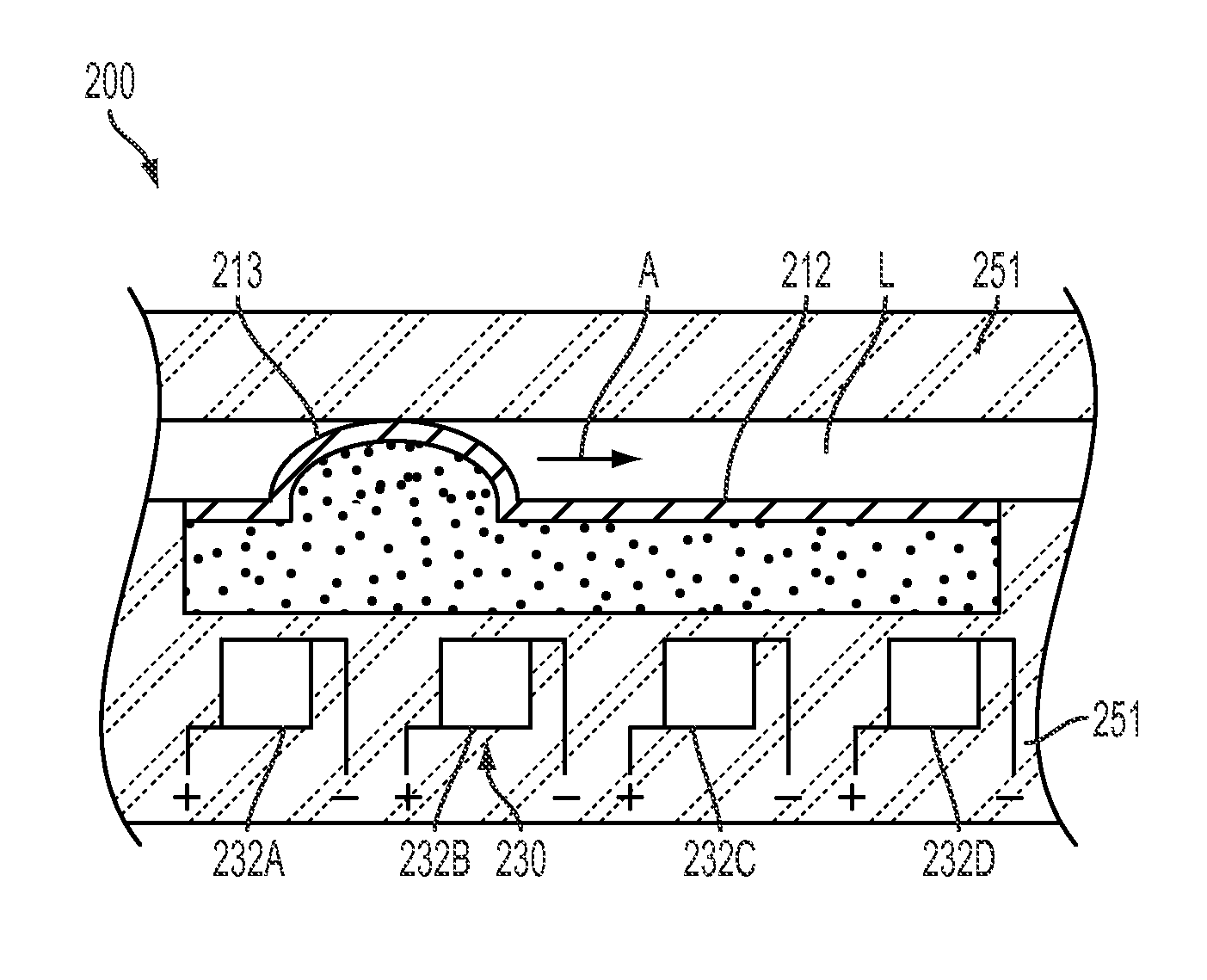
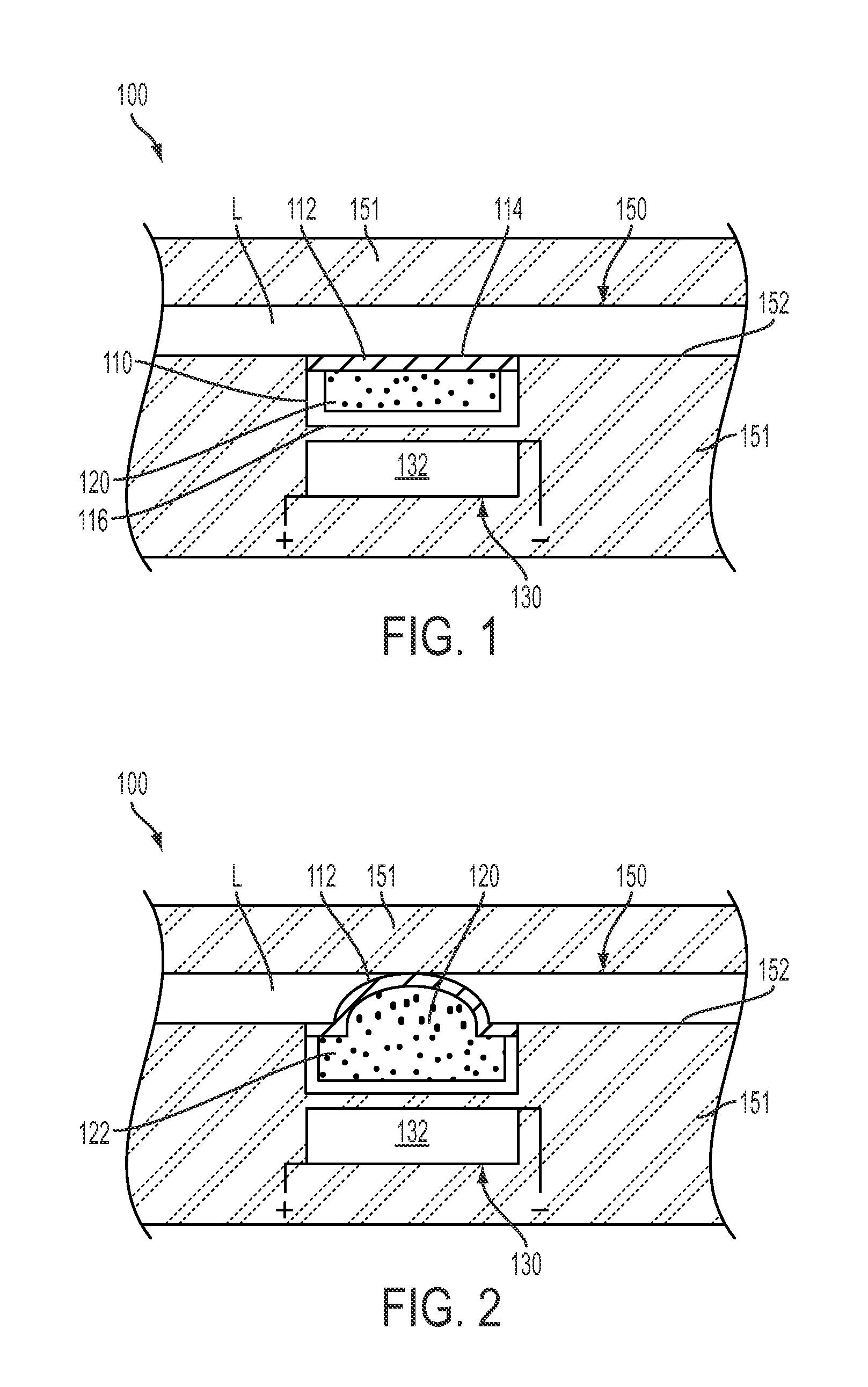
[0041]In another embodiment of the invention, a fluidic driven membrane is used for pressure surge control. The pressure surge control system has essentially the same arrangement and function as that shown in FIG. 1, except the flexible membrane expands into the flow channel in response to pressure surges that are detected in the system. A control system regulates the degree to which the membrane expands into the flow channel, the expansion being regulated as a function of pressure conditions or other variables. The system reduces or negates pressure surges by actively and dynamically altering the flow dimensions and shape of the flow in the pipe.


PUM


Abstract

A fluid conveyance system includes a flow passage and a cavity adjacent a side of the flow passage. A wall of the passage includes a flexible section that separates the cavity from the flow passage. The cavity contains a ferrofluidic material. The system further includes at least one magnetic field source positioned adjacent the flow channel. The magnetic field source is operable to move the ferrofluidic material in the cavity to exert a pressure on the flexible section and displace the flexible section into the flow passage to alter the flow of material through the passage. A method of collecting components from a sample volume includes the steps of distributing magnetic particles into the sample volume, capturing the components from the sample volume, and applying a magnetic field to the sample volume to control directional flow of the sample volume.

Description

CROSS REFERENCE TO RELATED APPLICATIONS[0001]This application claims priority under 35 U.S.C. §119 to U.S. Provisional Application No. 61 / 479,581, filed Apr. 27, 2011, the content of which is incorporated by reference herein in its entirety.FIELD OF THE INVENTION[0002]The present invention relates generally to fluid transport systems, and more specifically to fluid flow control systems that are driven by a ferrofluid and magnetic fields.BACKGROUND OF THE INVENTION[0003]Microfluidic devices are applied in various fields, including biotechnology, chemical analysis and clinical chemistry. A microfluidic system features a network of conduits, channels or hollows formed on a base plate of plastic, glass or silicon substrate. The sizes of the channels are very small, and the transport of microfluids can be affected by the surface tension of the fluid and the wettability of the wall surfaces.[0004]Current microfluidic systems utilize pneumatic, mechanical, and electromechanical or MEMS-bas...

Claims


Application Information

Patent Timeline
Patent Type & Authority Applications(United States)
IPC IPC(8): F04B43/04F15C1/00
CPCF04B43/04F16K99/0026F16K2099/0094F16K99/0061F16K2099/0084F16K99/0046Y10T137/206F04B43/14
Inventor SALSMAN, KENNETH
Owner SEMICON COMPONENTS IND LLC
Why Eureka
Try Eureka