
Apparatus and method for selective pixel binning

a selective pixel and pixel technology, applied in the field of apparatus and methods for selective pixel binning, can solve the problem of decreasing the depth image accuracy, and achieve the effect of preventing edge blurring and increasing the depth image accuracy

Active Publication Date: 2012-11-08
SAMSUNG ELECTRONICS CO LTD
View PDF9 Cites 11 Cited by
  • Summary
  • Abstract
  • Description
  • Claims
  • Application Information

AI Technical Summary

Benefits of technology

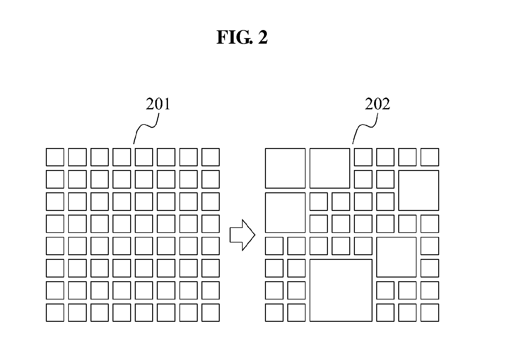
[0010]According to example embodiments, accuracy of a depth image may be increased by repeating binning of a pixel until an output level of the pixel reaches a predetermined threshold level.
[0011]According to other example embodiments, edge blurring may be prevented since a pixel determined as an edge through color information is excluded during the pixel binning.

Problems solved by technology

Here, when intensity of the reflected light is insufficient because a pixel size is too small or a distance between the object and the sensor is too great, the depth image becomes dark, accordingly decreasing accuracy of the depth image.

Method used


Image

  • Apparatus and method for selective pixel binning
  • Apparatus and method for selective pixel binning
  • Apparatus and method for selective pixel binning

Examples


Embodiment Construction

[0020]Reference will now be made in detail to example embodiments, examples of which are illustrated in the accompanying drawings, wherein like reference numerals refer to like elements throughout. Example embodiments are described below to explain the present disclosure by referring to the figures.

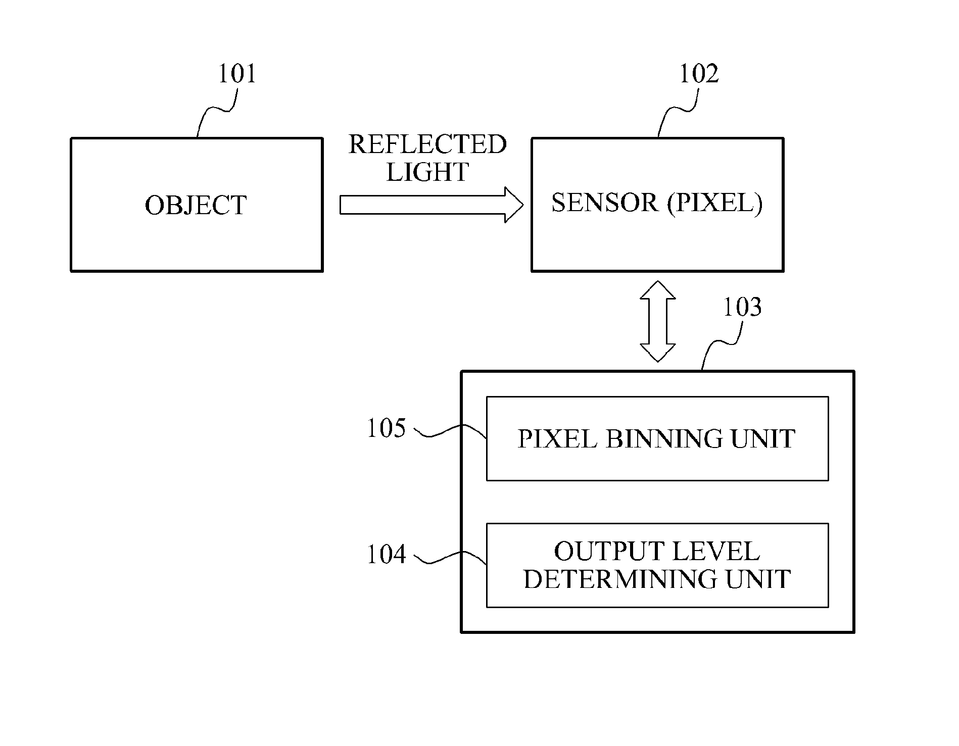
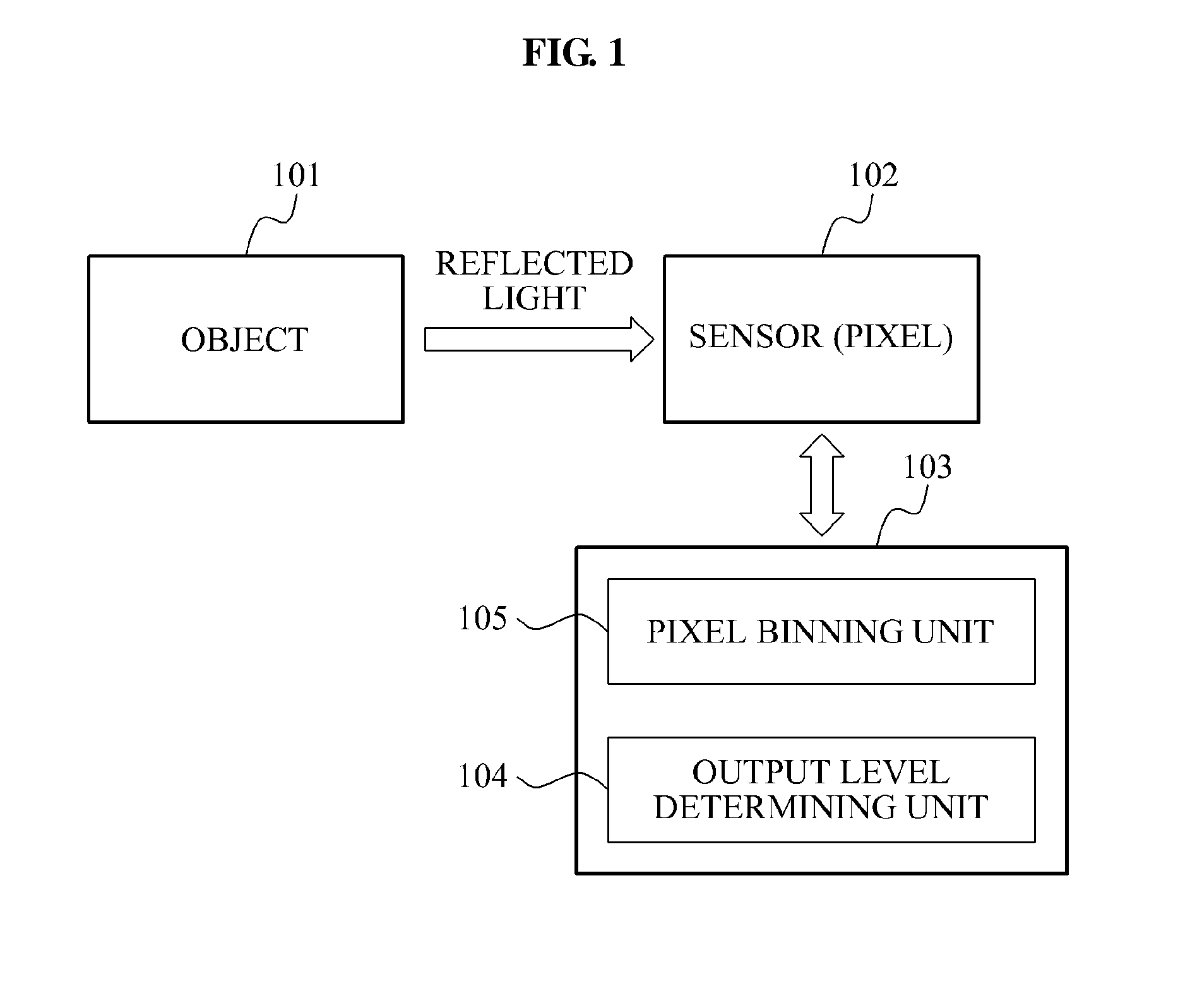
[0021]FIG. 1 illustrates an overall structure of a pixel binning apparatus 103 according to example embodiments.

[0022]Referring to FIG. 1, the pixel binning apparatus 103 may include an output level determining unit 104 and a pixel binning unit 105.

[0023]The output level determining unit 104 may determine an output level of a current pixel constituting a sensor 102. The current pixel refers to a pixel for extraction of a depth image, among a plurality of pixels constituting the sensor 102. Here, the output level of the current pixel may be determined by intensity of a light reflected from an object 101. The intensity of the reflected light may be determined by reflectance of the object 10...


PUM


Abstract

An output level of a pixel is determined using a reflected light reflected against an object. Pixel binning is selectively performed according to the output level of the pixel.

Description

CROSS-REFERENCE TO RELATED APPLICATIONS[0001]This application claims the priority benefit of Korean Patent Application No. 10-2011-0041436, filed on May 2, 2011, in the Korean Intellectual Property Office, the disclosure of which is incorporated herein by reference.BACKGROUND[0002]1. Field[0003]Example embodiments of the following description provide an apparatus and method for selectively binning a pixel to secure accuracy of a depth image.[0004]2. Description of the Related Art[0005]A sensor to acquire a depth image receives light reflected from an object. The depth image is acquired by measuring a quantity of electrons transferred to a float diffusion (FD) node included in a pixel that constitutes the sensor. The depth image may be determined using the measured quantity of electrons.[0006]Here, when intensity of the reflected light is insufficient because a pixel size is too small or a distance between the object and the sensor is too great, the depth image becomes dark, accordin...

Claims


Application Information

Patent Timeline
Patent Type & Authority Applications(United States)
IPC IPC(8): H04N5/217H04N23/40H04N25/00H04N25/46
CPCH04N5/351H04N5/347G01S17/894H04N25/50H04N25/46H04N25/00
Inventor KIM, SEONG JIN
Owner SAMSUNG ELECTRONICS CO LTD
Learn More