Vibration diaphragm and speaker with a vibration diaphragm

a technology of vibration diaphragm and vibration diaphragm, which is applied in the direction of transducer diaphragm, electromechanical transducer, instruments, etc., can solve the problems of affecting the sound quality of the speaker, the diaphragm with a considerable cavity depth disadvantages the compactness, and the volume of the speaker is limited by the diaphragm, so as to achieve the effect of improving rigidity

Inactive Publication Date: 2012-11-08
HI TECH SOUND SYST
View PDF4 Cites 32 Cited by
  • Summary
  • Abstract
  • Description
  • Claims
  • Application Information

AI Technical Summary

Benefits of technology

[0008]The main objective of the invention is to provide a vibration diaphragm that is mounted on a speaker and has a spherical surface area, an intervening annular area and an outer annular area. The vibration diaphragm has an improved rigidity.

Problems solved by technology

However, compactness of a volume of the speaker is limited by the diaphragm.
Insufficient rigidity of the diaphragm leads to undesirably irregular vibration negatively affecting sound quality of the speaker.
However the basin-shaped diaphragm with a considerable cavity depth disadvantages compactness thereof.
However, the basin-shaped configuration is not changed and still limits the compactness of the diaphragm.

Method used


Image

  • Vibration diaphragm and speaker with a vibration diaphragm
  • Vibration diaphragm and speaker with a vibration diaphragm
  • Vibration diaphragm and speaker with a vibration diaphragm

Examples


Embodiment Construction

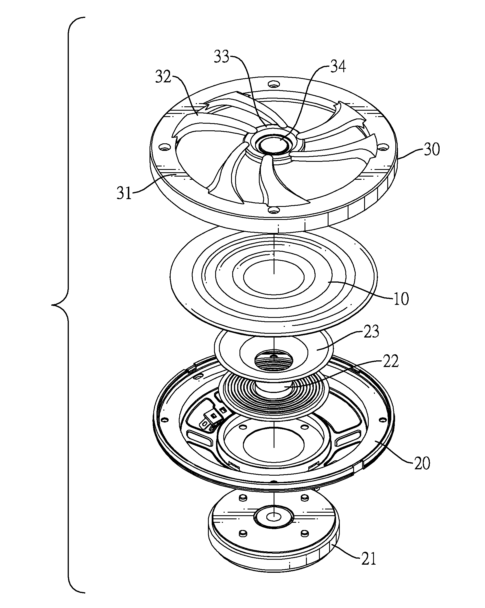
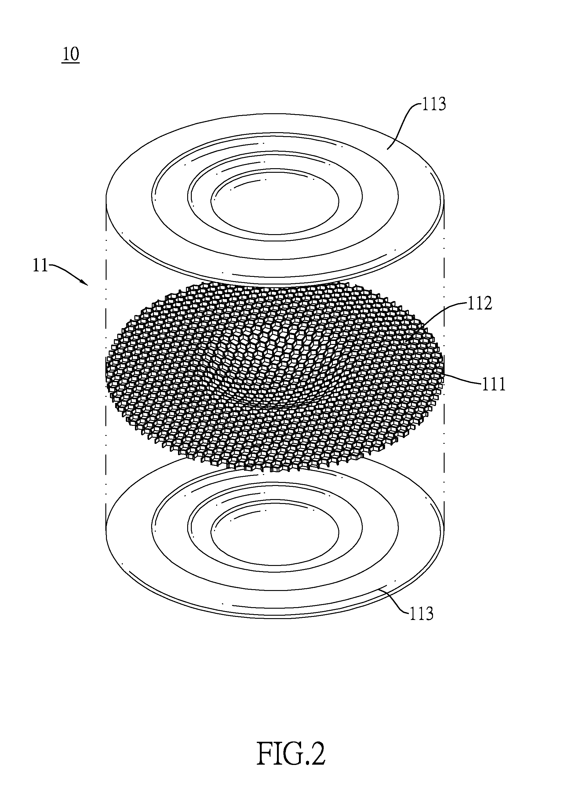
[0016]With reference to FIG. 1, a vibration diaphragm 10 for a speaker in accordance with the present invention comprises a circular board body 11 being sufficiently thin and having a spherical bowl section 12, an annular intervening section 13 and an annular outer section 14.

[0017]The spherical bowl section 12 has a top and a spherical cavity defined in the top.

[0018]The annular intervening section 13 is a ring-shaped board, may have a flat outer surface without any recesses or protrusions, and is formed on and protrudes radially and horizontally outward from the spherical bowl section 12. A bending line is formed on a boundary between the spherical bowl section 12 and the annular intervening section 13 to improve rigidity of the vibration diaphragm 10.

[0019]The annular outer section 14 is a ring-shaped board, may have a flat outer surface without any recesses or protrusions, and is formed on and protrudes radially from the annular intervening section 13 and extends obliquely outwa...


PUM


Abstract

A vibration diaphragm for a speaker has a spherical bowl section, an annular intervening section and an annular outer section. The spherical bowl section has a top and a spherical cavity defined in the top. The annular intervening section is formed on and protrudes radially outward from the spherical bowl section. A bending line is formed on a boundary between the spherical bowl section and the annular intervening section. An annular outer section is formed on and protrudes radially from the annular intervening section and extends obliquely outward in a direction along which the cavity is sunk, wherein a bending line is formed on a boundary between the annular intervening section and the annular outer section, and an obtuse angle is defined between the annular intervening section and annular outer section.

Description

BACKGROUND OF THE INVENTION[0001]1. Field of the Invention[0002]The present invention relates to a vibration diaphragm, and more particularly to a vibration diaphragm that is mounted on a speaker and has a spherical surface area, an intervening annular area and an outer annular area. The vibration diaphragm has an improved rigidity.[0003]2. Description of Related Art[0004]A conventional speaker comprises a frame, a magnet, a coil and a diaphragm. The magnet is mounted on the frame. The coil is located around one of the magnetic poles of the magnet and is selectively electrified. The diaphragm is mounted on the frame and is connected to the coil. When electrified, the coil generates a magnetic field to interact with a magnetic field of the magnet so that the coil and the diaphragm are vibrated. The vibrating diaphragm causes sound wave.[0005]Improved speakers that are more compact are developed for being mounted in automobiles or embedded in walls. However, compactness of a volume of...

Claims


Application Information

Patent Timeline
Patent Type & Authority Applications(United States)
IPC IPC(8): H04R1/00H04R7/02
CPCH04R7/122H04R2307/029H04R2307/025H04R7/125
Inventor LIN, STEFF
Owner HI TECH SOUND SYST
Why Eureka
Try Eureka